 New Sign for the Plasticville
Frosty
Bar
 New Sign for the Plasticville
Frosty
Bar
 The
sign is available on Thingiverse where you can customize it and create
an stl file which can be sent to one of the on-line 3D print shops : https://www.thingiverse.com/thing:3159254 The
sign is available on Thingiverse where you can customize it and create
an stl file which can be sent to one of the on-line 3D print shops : https://www.thingiverse.com/thing:3159254 |
 Original Sign. I got out my calipers and measured each feature on the sign. I did the measurements in millimeters since that is the standard unit of measurement used in the 3D modeling program I used. After doing a few, it was clear that Bachmann built the original molds using English measurement. Every measurement was coming out the MKS equivalent of 1/4 inch, 1/8 inch, 3/16 inch, etc. There are many programs that can be used for 3D modeling. For this project, I used the OpenSCAD program. I really like this method of modeling because it is programmatic. I used it for my P&LE Locomotive Shop which has thousands of individual bricks. I didn't have to construct each one. I used computer code to do one and then repeated it over and over in a code loop. For this sign, I created the OpenSCAD code in about an hour - though it took a few tweaks and several test prints to get the results that I wanted. |
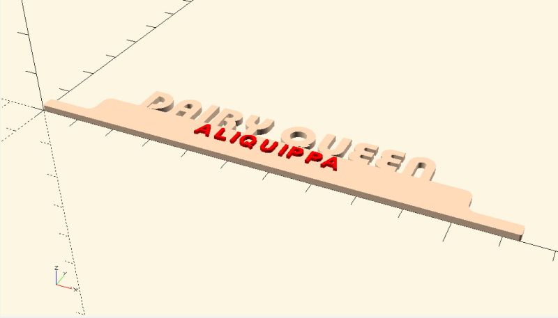 Here is screen capture of the sign by OpenSCAD. Fonts were a problem especially for the "Frosty Bar" font. I found that the town name was pretty close to "Arial" but the Frosty Bar sign did not match any font that I had available or any font that I could find. I ended up choosing the font "Pump Demi Bold LET". I adjusted the "spacing" parameter to try to match the original sign as well as I could. Let me know if you have any information about the font used on the "Frosty Bar" sign. In OpenSCAD, you create 2D objects which you extrude into 3 dimensions or you can create 3D objects directly. I created the basic sign shape from a polygon which I then extruded. I used the "offset" command to make the small fillets at the left and right edges of the sign. To create the "inner" fillets on the left and right inside corners I used a cylinder subtracted from a cube. Look at the "difference" command in the code. The color in this rendering is false. I ended up painting the sign. This step produces an ".stl" file which is used in the next step. |
|
Here is a listing
of the Plasticville
Frosty Bar Sign.scad file:
// |
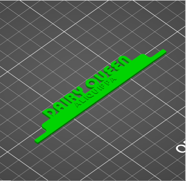 The slicer program that I use with my Original Prusa i3 MK2s is "Slic3r". A customized version of that program is provided by Prusa. Slic3r reads the *.stl file created by OpenSCAD and slices the design. Output is a "*.gcode" file which is then sent to the 3D printer. I used the default slicer setting in Slic3r provided by Prusa. It is called "0.15mm OPTIMAL". |
 Here is the sign as printed. Still on the print bed. I used white PLA because I had it. Since the sign was going to be painted, it didn't matter too much what color PLA was used. Took about an hour to print. |
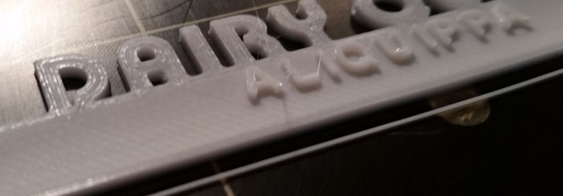 Here is a close up of the sign. You can see the lines of PLA as laid down by the printer. This type of printing does not produce the nice smooth results of the injection molding of the original Bachmann products. Painting helps hide these lines. Other people talk about sanding the object with 200 to 3000 grit sandpaper to remove some of the lines but I've not tried that. |
 Even though I used white PLA, I still painted the sign white. That paint (from WalMart) helped smooth out the surface. I painted the tops of the red letters of Aliquippa. |
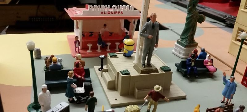 Here is the sign in place on the Frosty Bar in the park on my layout (now christened Dairy Queen). |
 New Sign for the Plasticville
Frosty
Bar V2
New Sign for the Plasticville
Frosty
Bar V2I found a photo of an actual Dairy Queen sign. Then I found a photo of the words "DAIRY QUEEN" in the correct font. Then I found a photo of a Dairy Queen ice cream cone.
I used those photos along with the surface command to make a pretty reasonable representation in OpenSCAD of an actual Dairy Queen sign.
I rendered it and then input it into the Prusa slicer. I then laid the sign flat on the printbed. I had to use supports under the cone since it does not touch the printbed.
Along with the OpenSCAD code, you need the files "DQ_1950s_logo - edited.png" and "Dairy Queen Ice Cream Cone Sign - edited.png" (all available below). I edited each of those images to be black and white which work perfectly with the "surface" command in OpenSCAD.
I printed in white PLA but you can use any color as the sign will have to be painted in any case.
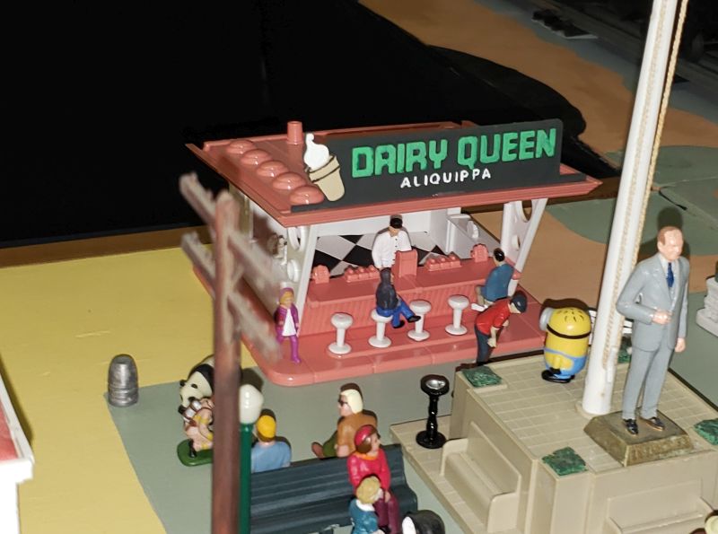 This is a photo of the new sign on my layout. |
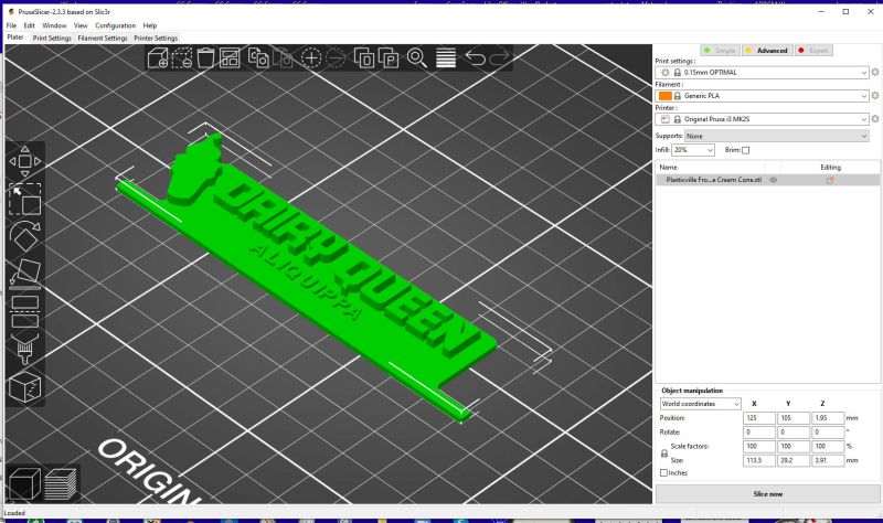 Prusa Slicer |
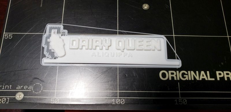 On the printbed. You can see the supports generated underneath the ice cream code. |
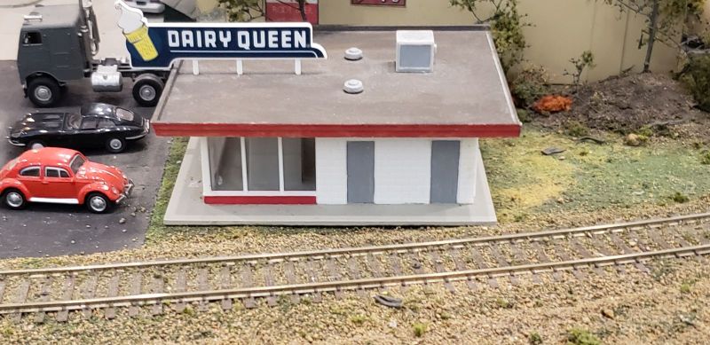 There is one really nice model of a Dairy Queen on the HO layout of the North County Model Railroad Society (NCMRS) in Oceanside, CA. |
 There is a photo of a Dairy Queen sign taken in Ottawa. |
Here is a listing
of the Plasticville Frosty Bar Sign - Correct Font and Ice Cream Cone.scad file:// |
 DQ_1950s_logo - edited.png Needed for the OpenSCAD code. |
 Needed for the OpenSCAD code. |
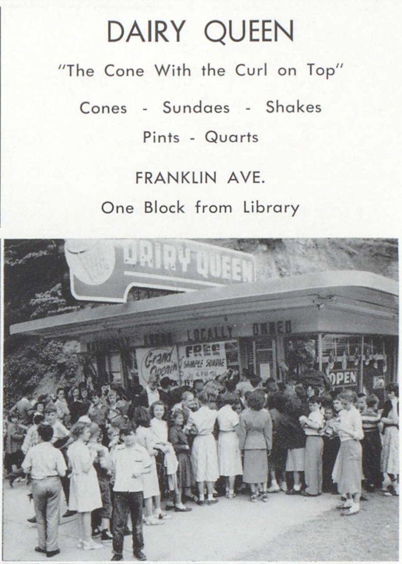 This black and white photo is from the 1954 yearbook of my hometown, Aliquippa, PA. This DQ was a popular place in the 50's and 60's. The building is still there but now houses an architect. I was 6 years old when this picture was taken, so I'm pretty sure that I and not in it. |
 New Sign for
the Plasticville Turnpike
 The
sign is available on Thingiverse where you can customize it and create
an stl file which can be sent to one of the on-line 3D print shops : https://www.thingiverse.com/thing:3189546 The
sign is available on Thingiverse where you can customize it and create
an stl file which can be sent to one of the on-line 3D print shops : https://www.thingiverse.com/thing:3189546 |
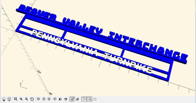 Here is the sign as it appears in OpenSCAD. The colors are false. |
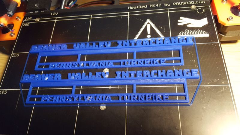 Here is the print, still on the print bed. I printed with blue PLA to save some painting. The blue does not exactly match the blue of the turnpike buildings. But close enough for now. I printed at 100% fill with 3 perimeters - otherwise using the Prusa defaults for "Original Prusa i3 MK2" and "0.15 mm OPTIMAL" print settings. I put two copies of the sign on the print bed since two are needed for the Turnpike. Took about 3 hours to print both signs. |
|
Here is a listing
of the Plasticville
Turnpike Sign.scad file:
// |
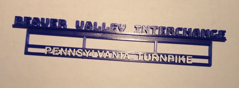 I painted the turnpike name white to match what Bachmann did on the original turnpike. |
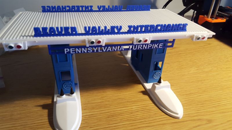 Here is the updated Pennsylvania Turnpike sign at the Beaver Valley Interchange, about 20 miles from my childhood home in Aliquippa, PA. |
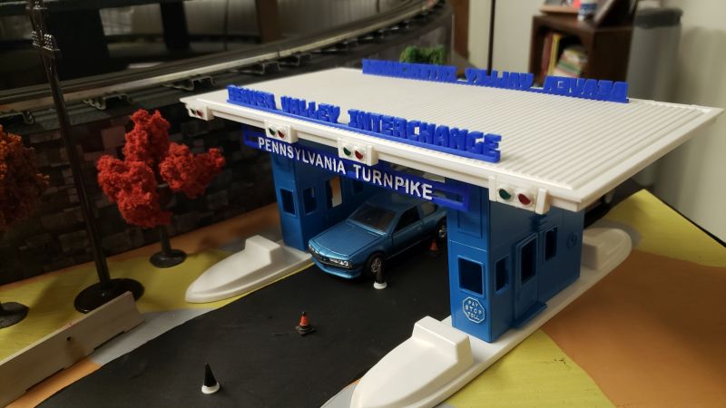 Here it is on my layout. |
 Grade
Crossing
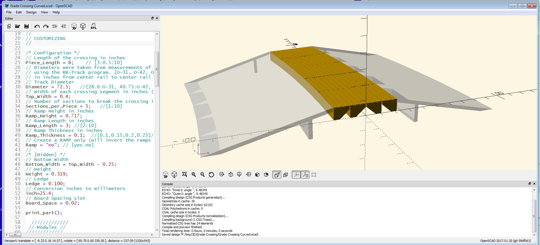
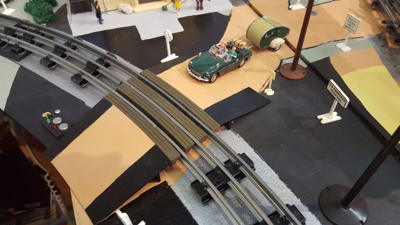
 The grade crossing is available on Thingiverse where you can customize it and create
an stl file which can be sent to one of the on-line 3D print shops. The grade crossing is available on Thingiverse where you can customize it and create
an stl file which can be sent to one of the on-line 3D print shops.The curved version is at : https://www.thingiverse.com/thing:2832224 and the straight version is at: https://www.thingiverse.com/thing:3193426 |
//
// Customizable Curved Grade Crossing - Lionel O Tubular Track
// Mark DiVecchio
// March 2018
// Original development using OpenSCAD 2017.01.20
//
// This SCAD script is licensed under a
// Creative Commons Attribution-NonCommercial 3.0 Unported License.
//
// V1.0 - original release
// V2.0 - adds ramps
//
// http://www.silogic.com/trains/layout.html
//
// in slicer, rotate y = 180 deg, rotate z = 45 deg (to get long print lines)
// use 2 bottom layers, 0 top layers, rectilinear bottom layers
//
$fn=200*1;
//
// CUSTOMIZING
//

/* Configuration */
// Length of the crossing in inches
Piece_Length = 6; // [3:0.5:10]
// Diameters were taken from measurements of circles
// using the RR-Track program. [O-31, O-42, O-54, O-72]
// in inches from center rail to center rail
// Track Diameter
Diameter = 72.5; //[28.6:O-31, 40.75:O-42, 53.3:O-54, 72.5:O-72]
// Width of each crossing segment in inches (Leave enough space for the wheel flanges)
Top_Width = 0.4;
// Number of sections to break the crossing into
Sections_per_Piece = 5; //[1:10]
// Create grade crossing or ramp (will invert the ramps for printing)?
To_Print = "grade"; // [grade,ramp]
// Ramp Height in inches
Ramp_Height = 0.717;
// Ramp Length in inches
Ramp_Length = 3; //[2:10]
// Ramp Thickness in inches
Ramp_Thickness = 0.1; //[0.1,0.15,0.2,0.25]//
//
/* [Hidden] */
// Bottom Width
Bottom_Width = Top_Width - 0.25;
// Height
Height = 0.319;
// Ledge
Ledge = 0.100;
// Conversion inches to millimeters
inch=25.4;
// Board Spacing slot
Board_Space = 0.02;

print_part();

 /////////////
 // Modules //
/////////////

module print_part() {

translate([ -(Diameter * inch)/2, 0, 0 ])
 {
 if (To_Print == "grade") difference() {
 union () {
 translate([0,0,0])
 InnerCurvedCrossing(Diameter);
 translate([Board_Space * inch,0,0])
 OuterCurvedCrossing(Diameter);
 translate([(Board_Space * 1) * -1 * inch,0,0])
 Inner2CurvedCrossing(Diameter);
 translate([(Board_Space * 2) * 1 * inch,0,0])
 Outer2CurvedCrossing(Diameter);
 }

 union () {
 for (chunks = [1 : Sections_per_Piece]) {
 rotate([0,0,(Piece_Length* chunks/Sections_per_Piece) / (2 * 3.14159 * (Diameter/2)) * 360]) Slots();
 }
 }
 }
 if (To_Print == "ramp") {
 rotate([180, 0, 0]) {
 translate([0,0,0])
 InnerCurvedRamp(Diameter);
 translate([0,0,0])
 OuterCurvedRamp(Diameter);
 }
 }
 if (To_Print == "grade") {
 %translate([0,0,0])
 InnerCurvedRamp(Diameter);
 %translate([0,0,0])
 OuterCurvedRamp(Diameter);
 }
 }
}

module InnerCurvedRamp(D) {
 translate([0,, 0, -(Ramp_Height - Height) * inch])
 rotate_extrude(angle=(Piece_Length / (2 * 3.14159 * (D/2))) * 360)
 translate([(D/2 - (2 *Top_Width) - (2 * Board_Space) - Ramp_Length) * inch, 0, 0])
 rotate([0, 0, To_Print=="ramp" ? -atan(Ramp_Height/Ramp_Length): 0])
 polygon([[0,0],
 [Ramp_Length * inch, Ramp_Height * inch],
 [Ramp_Length * inch, (Ramp_Height - Ramp_Thickness) * inch],
 [(Ramp_Length - 0.5) * inch, (Ramp_Height - Ramp_Thickness - (0.5) * (Ramp_Height / Ramp_Length)) * inch],
 [(Ramp_Length - 0.5) * inch, 0],
 [(Ramp_Length - 0.5 - Ramp_Thickness) * inch, 0],
 [(Ramp_Length - 0.5 - Ramp_Thickness) * inch, (Ramp_Height - Ramp_Thickness - (0.5 + Ramp_Thickness) * (Ramp_Height / Ramp_Length)) * inch],
 [(Ramp_Thickness * Ramp_Length / Ramp_Height) * inch, 0]
 ]);
}

module OuterCurvedRamp(D) {
 translate([0,, 0, -(Ramp_Height - Height) * inch])
 rotate_extrude(angle=(Piece_Length / (2 * 3.14159 * (D/2))) * 360)
 translate([(D/2 + (2 *Top_Width) + (3 * Board_Space) + Ramp_Length) * inch, 0, 0])
 rotate([0,180,0])
 rotate([0, 0, To_Print =="ramp" ? -atan(Ramp_Height/Ramp_Length): 0])
 polygon([[0,0],
 [Ramp_Length * inch, Ramp_Height * inch],
 [Ramp_Length * inch, (Ramp_Height - Ramp_Thickness) * inch],
 [(Ramp_Length - 0.5) * inch, (Ramp_Height - Ramp_Thickness - (0.5) * (Ramp_Height / Ramp_Length)) * inch],
 [(Ramp_Length - 0.5) * inch, 0],
 [(Ramp_Length - 0.5 - Ramp_Thickness) * inch, 0],
 [(Ramp_Length - 0.5 - Ramp_Thickness) * inch, (Ramp_Height - Ramp_Thickness - (0.5 + Ramp_Thickness) * (Ramp_Height / Ramp_Length)) * inch],
 [(Ramp_Thickness * Ramp_Length / Ramp_Height) * inch, 0]
 ]);
}


module InnerCurvedCrossing(D) {
// Main Inner curved body
echo("Inner: angle ", (Piece_Length / (2 * 3.14159 * (D/2))) * 360);
 rotate_extrude(angle=(Piece_Length / (2 * 3.14159 * (D/2))) * 360)
 translate([(D/2 - Top_Width) * inch,0,0])
 rotate([0, 0, 0])
 polygon([[0,0], // 1
 [0,(Height) * inch], // 2
 [((Top_Width/3) - Board_Space)* inch,(Height) * inch], // a
 [((Top_Width/3) - Board_Space)* inch,(Height - Board_Space) * inch], // b
 [((Top_Width/3))* inch,(Height - Board_Space) * inch], // c
 [((Top_Width/3))* inch,(Height) * inch], // d
 [((Top_Width * 2 / 3) - Board_Space)* inch,(Height) * inch], // e
 [((Top_Width * 2 / 3) - Board_Space)* inch,(Height - Board_Space) * inch], // f
 [((Top_Width * 2 / 3))* inch,(Height - Board_Space) * inch], // g
 [((Top_Width * 2 / 3))* inch,(Height) * inch], // h
 [(Top_Width) * inch, (Height) * inch], // 3
 [(Top_Width) * inch,(Height - Ledge) * inch], // 4
 [(Bottom_Width) *inch, 0]]); // 5
}

module OuterCurvedCrossing(D) {
// Main Outer curved body
echo("Outer: angle ", (Piece_Length / (2 * 3.14159 * (D/2))) * 360);
 rotate_extrude(angle=(Piece_Length / (2 * 3.14159 * (D/2))) * 360)
 translate([(D/2 + Top_Width) * inch,0,0])
 rotate([0,180,0])
 polygon([[0,0], // 1
 [0,(Height) * inch], // 2
 [((Top_Width/3) - Board_Space)* inch,(Height) * inch], // a
 [((Top_Width/3) - Board_Space)* inch,(Height - Board_Space) * inch], // b
 [((Top_Width/3))* inch,(Height - Board_Space) * inch], // c
 [((Top_Width/3))* inch,(Height) * inch], // d
 [((Top_Width * 2 / 3) - Board_Space)* inch,(Height) * inch], // e
 [((Top_Width * 2 / 3) - Board_Space)* inch,(Height - Board_Space) * inch], // f
 [((Top_Width * 2 / 3))* inch,(Height - Board_Space) * inch], // g
 [((Top_Width * 2 / 3))* inch,(Height) * inch], // h
 [(Top_Width) * inch, (Height) * inch],
 [(Top_Width) * inch,(Height - Ledge) * inch],
 [(Bottom_Width) *inch, 0]]);
}
module Slots() {
 translate([0,Board_Space/2 * inch, ((Board_Space/2) + Height - Board_Space) * inch])
 rotate([0, 90, 0])
 linear_extrude(height = (Diameter/2 + (Top_Width * 4)) * inch)
 square(size = Board_Space * inch, center = true);

}
module Inner2CurvedCrossing(D) {
// Main Inner curved body
echo("Inner2: angle ", (Piece_Length / (2 * 3.14159 * (D/2))) * 360);
 rotate_extrude(angle=(Piece_Length / (2 * 3.14159 * (D/2))) * 360)
 translate([(D/2 - (Top_Width * 2)) * inch,0,0])
 polygon([[0,0], // 1
 [0,(Height) * inch], // 2
 [((Top_Width/3) - Board_Space)* inch,(Height) * inch], // a
 [((Top_Width/3) - Board_Space)* inch,(Height - Board_Space) * inch], // b
 [((Top_Width/3))* inch,(Height - Board_Space) * inch], // c
 [((Top_Width/3))* inch,(Height) * inch], // d
 [((Top_Width * 2 / 3) - Board_Space)* inch,(Height) * inch], // e
 [((Top_Width * 2 / 3) - Board_Space)* inch,(Height - Board_Space) * inch], // f
 [((Top_Width * 2 / 3))* inch,(Height - Board_Space) * inch], // g
 [((Top_Width * 2 / 3))* inch,(Height) * inch], // h
 [(Top_Width) * inch, (Height) * inch],
 [(Top_Width) * inch,(Height - Ledge) * inch],
 [(Bottom_Width) *inch, 0]]);
}

module Outer2CurvedCrossing(D) {
// Main Outer curved body
echo("Outer2: angle ", (Piece_Length / (2 * 3.14159 * (D/2))) * 360);
 rotate_extrude(angle=(Piece_Length / (2 * 3.14159 * (D/2))) * 360)
 translate([(D/2 + (Top_Width * 2)) * inch,0,0])
 rotate([0,180,0])
 polygon([[0,0], // 1
 [0,(Height) * inch], // 2
 [((Top_Width/3) - Board_Space)* inch,(Height) * inch], // a
 [((Top_Width/3) - Board_Space)* inch,(Height - Board_Space) * inch], // b
 [((Top_Width/3))* inch,(Height - Board_Space) * inch], // c
 [((Top_Width/3))* inch,(Height) * inch], // d
 [((Top_Width * 2 / 3) - Board_Space)* inch,(Height) * inch], // e
 [((Top_Width * 2 / 3) - Board_Space)* inch,(Height - Board_Space) * inch], // f
 [((Top_Width * 2 / 3))* inch,(Height - Board_Space) * inch], // g
 [((Top_Width * 2 / 3))* inch,(Height) * inch], // h
 [(Top_Width) * inch, (Height) * inch],
 [(Top_Width) * inch,(Height - Ledge) * inch],
 [(Bottom_Width) *inch, 0]]);
}
//
// Customizable Straight Grade Crossing - Lionel O Tubular Track
// Mark DiVecchio
// March 2018
// Original development using OpenSCAD 2017.01.20
//
// This SCAD script is licensed under a
// Creative Commons Attribution-NonCommercial 3.0 Unported License.
//
// V1.0 - Original release
// V2.0 - adds ramps
//
// http://www.silogic.com/trains/layout.html
//
// in slicer, rotate y = 180 deg, rotate z = 45 deg (to get long print lines)
// use 2 bottom layers, 0 top layers, rectilinear bottom layers

$fn=200*1;
//
// CUSTOMIZING
//
/* Configuration */
// Length of the crossing in inches
Piece_Length = 6.0; // [3:0.5:10]
// Width of each crossing segment in inches (Leave enough space for the wheel flanges)
Top_Width = 0.4;
// Number of sections to break the crossing into
Sections_per_Piece = 5; //[1:10]
// Create grade crossing or ramp (will invert the ramps for printing)?
To_Print = "grade"; // [grade,ramp]
// Ramp Height in inches
Ramp_Height = 0.717;
// Ramp Length in inches
Ramp_Length = 3; //[2:10]
// Ramp Thickness in inches
Ramp_Thickness = 0.1; //[0.1,0.15,0.2,0.25]
//
/* [Hidden] */
// Bottom Width
Bottom_Width = Top_Width - 0.25;
// Height of segment - based on measured tubular track
Height = 0.319;
// Ledge
Ledge = 0.100;
// Conversion inches to millimeters
inch=25.4;
// Board Spacing slot
Board_Space = 0.02;

print_part();

 /////////////
 // Modules //
/////////////

module print_part() {

translate([ -(((2 * Top_Width) + Board_Space) * inch), 0, 0 ]) {
 if (To_Print == "grade") difference() {
 union () {
 StraightCrossingInner(0, 0 * (Top_Width + Board_Space));
 StraightCrossingInner(0, 1 * (Top_Width + Board_Space));
 StraightCrossingOuter(180, 2 * (Top_Width + Board_Space));
 StraightCrossingOuter(180, 3 * (Top_Width + Board_Space));
 }
 union () {
 for (chunks = [1 : Sections_per_Piece]) {
 translate ([0, ((Piece_Length * chunks/Sections_per_Piece) - Board_Space) * inch, 0]) Slots();
 }
 }
 }
 if (To_Print == "ramp") {
 rotate([180, 0, 0]) {
 StraightRamp(0,0);
 StraightRamp(180, ((2 * (Ramp_Length)) + Board_Space) + 4 * (Top_Width + Board_Space));
 }
 }
 if (To_Print == "grade") {
 %StraightRamp(0,0);
 %StraightRamp(180, ((2 * (Ramp_Length)) + Board_Space) + 4 * (Top_Width + Board_Space));
 }
 }
}

module StraightRamp(Angle, Mvmt) {
// Ramp up
translate([(-Ramp_Length - Board_Space) * inch, Piece_Length * inch, -(Ramp_Height - Height) * inch])
 rotate([90, 0, 0])
 linear_extrude(height = Piece_Length * inch)
 translate([(Mvmt) * inch, 0, 0])
 rotate([0, Angle, 0])
 rotate([0, 0, To_Print =="ramp" ? -atan(Ramp_Height/Ramp_Length): 0])
 polygon([[0,0],
 [Ramp_Length * inch, Ramp_Height * inch],
 [Ramp_Length * inch, (Ramp_Height - Ramp_Thickness) * inch],
 [(Ramp_Length - 0.5) * inch, (Ramp_Height - Ramp_Thickness - (0.5) * (Ramp_Height / Ramp_Length)) * inch],
 [(Ramp_Length - 0.5) * inch, 0],
 [(Ramp_Length - 0.5 - Ramp_Thickness) * inch, 0],
 [(Ramp_Length - 0.5 - Ramp_Thickness) * inch, (Ramp_Height - Ramp_Thickness - (0.5 + Ramp_Thickness) * (Ramp_Height / Ramp_Length)) * inch],
 [(Ramp_Thickness * Ramp_Length / Ramp_Height) * inch, 0]
 ]);
}

module StraightCrossingInner(Angle, Mvmt) {
// Main straight body
 translate([0, Piece_Length * inch, 0])
 rotate([90, 0, 0])
 linear_extrude(height = Piece_Length * inch)
 translate([(Mvmt) * inch, 0, 0])
 rotate([0, Angle, 0])
 polygon([[0,0], // 1
 [0,(Height) * inch], // 2
 [((Top_Width/3) - Board_Space)* inch,(Height) * inch], // a
 [((Top_Width/3) - Board_Space)* inch,(Height - Board_Space) * inch], // b
 [((Top_Width/3))* inch,(Height - Board_Space) * inch], // c
 [((Top_Width/3))* inch,(Height) * inch], // d
 [((Top_Width * 2 / 3) - Board_Space)* inch,(Height) * inch], // e
 [((Top_Width * 2 / 3) - Board_Space)* inch,(Height - Board_Space) * inch], // f
 [((Top_Width * 2 / 3))* inch,(Height - Board_Space) * inch], // g
 [((Top_Width * 2 / 3))* inch,(Height) * inch], // h
 [(Top_Width) * inch, (Height) * inch], // 3
 [(Top_Width) * inch,(Height - Ledge) * inch], // 4
 [(Bottom_Width) *inch, 0]]); // 5
}
module StraightCrossingOuter(Angle, Mvmt) {
// Main straight body
 translate([0, Piece_Length * inch, 0])
 rotate([90, 0, 0])
 linear_extrude(height = Piece_Length * inch)
 translate([(Mvmt + Top_Width) * inch, 0, 0])
 rotate([0, Angle, 0])
 polygon([[0,0], // 1
 [0,(Height) * inch], // 2
 [((Top_Width/3) - Board_Space)* inch,(Height) * inch], // a
 [((Top_Width/3) - Board_Space)* inch,(Height - Board_Space) * inch], // b
 [((Top_Width/3))* inch,(Height - Board_Space) * inch], // c
 [((Top_Width/3))* inch,(Height) * inch], // d
 [((Top_Width * 2 / 3) - Board_Space)* inch,(Height) * inch], // e
 [((Top_Width * 2 / 3) - Board_Space)* inch,(Height - Board_Space) * inch], // f
 [((Top_Width * 2 / 3))* inch,(Height - Board_Space) * inch], // g
 [((Top_Width * 2 / 3))* inch,(Height) * inch], // h
 [(Top_Width) * inch, (Height) * inch], // 3
 [(Top_Width) * inch,(Height - Ledge) * inch], // 4
 [(Bottom_Width) *inch, 0]]); // 5
}
module Slots() {
 translate([0, 0, (Height - Board_Space) * inch])
 cube([(Board_Space + Top_Width) * 4 * inch, Board_Space * inch, Board_Space * inch]);
}
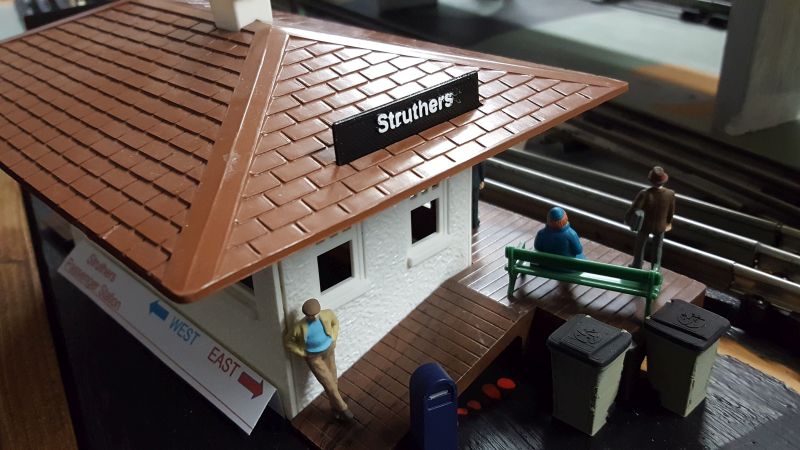
 Station Signs
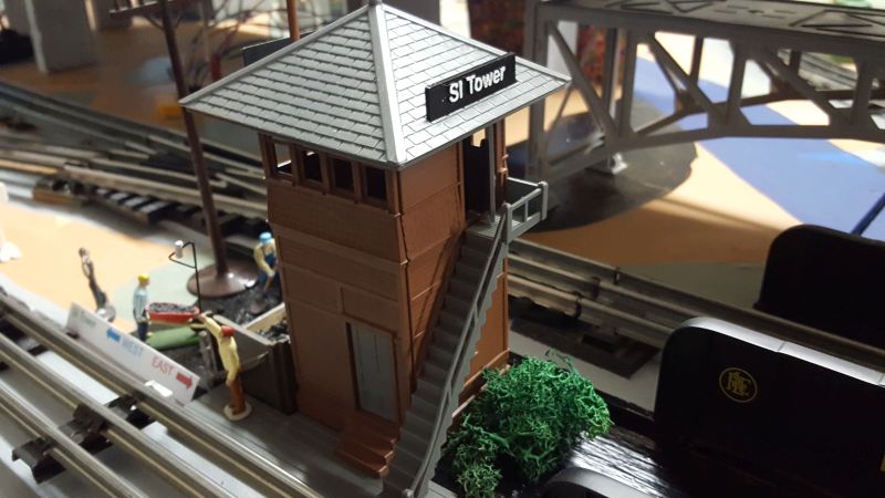
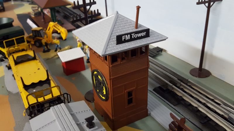
 Tower Signs
 Stairs
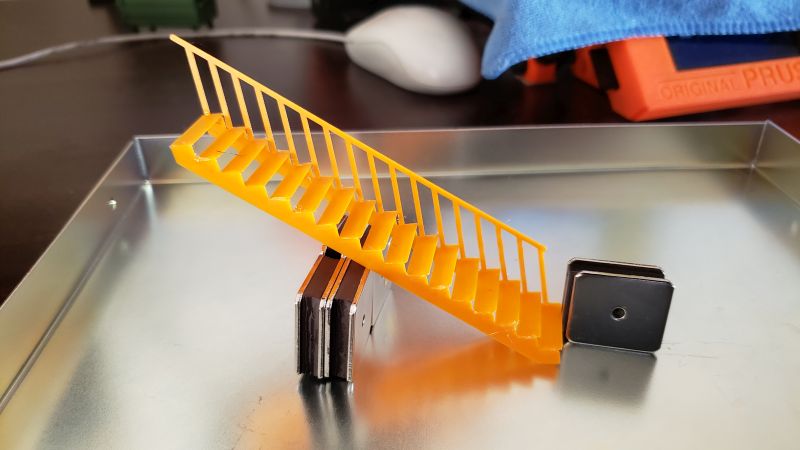
Some combinations of setting of the physical parameters of the stairs may not be buildable in the real world and some may crash the OpenSCAD program.
Stair values from this web page:
https://www.calculator.net/stair-calculator.html
Use the "Comprehensive Version" of the Stair Calculator.
This program is capable of building every stair possible. I believe that if you always make the Total Rise equal to an integral multiple of the Rise, the program will be able to build the stair.
Enter your values into the equations on that web page. Select the "Use One Run" tab. Set "Fixed Rise", "Has tread", "No headroom restriction" and "Standard stringer mount" Also enter values here for Run, Total Rise, Rise and Tread thickness. Enter a Thread thickness of 1 inch. Then press "Calculate".
Enter the Results from that web page into this script's customizer. You may have to renter the Rise if the calculator could not work with your suggested Rise. The Stairs OpenSCAD program does not need every Result value.
More information about stairs equations:
https://www.jlconline.com/training-the-trades/stair-stringers-calculation-and-layout_o
Uses Build Plate from the Thingiverse library.
3D printers may have a hard time with HO and N part thickness. G
scale stairs may not fit on a typical build plate and each part of the
stairs may have to be printed individually.
 K-Rail (Barrier Rail)
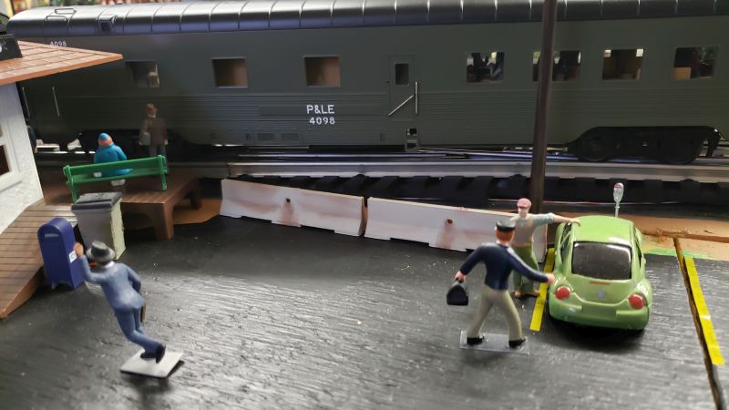
A K-Rail print done for my O Gauge (1/4 inch to the foot) toy
train layout. Roughly based on a "Jensen Precast 10' Barrier Rail with
Fence Post Holes" except that I made it 12' 7" long.
You can find the Jensen spec for this K-Rail with an internet search.
email : markd@silogic.com
The DiVecchio
genealogy home page
The Frazzini
genealogy home page
This site will be under construction for a while.
