As I mentioned in the posts on the forum, I am releasing these programs and documentation under the GNU GENERAL PUBLIC LICENSE Version 3 and GNU Free Documentation License Version 1.3. These licenses permit anyone to use the program and the documentation to produce follow on programs as long as those programs remain covered by the GNU licenses.
The Free
Software Foundation
web page talks about what "free software" means.
For more information, look on the Open Source Initiative web site which includes a description of what Open Source means and their certification of the GPL version 3.
Here is the copyright notice for those two licenses:GNU GPL
Remote Train Control Program for Windows
© Copyright 2015 by Mark DiVecchio
Remote Train Control is free software: you can redistribute it and/or modify it under the terms of the GNU General Public License as published by the Free Software Foundation, either version 3 of the License, or (at your option) any later version.
Remote Train Control is distributed in the hope that it will be useful, but WITHOUT ANY WARRANTY; without even the implied warranty of MERCHANTABILITY or FITNESS FOR A PARTICULAR PURPOSE. See the GNU General Public License for more details.
You should have received a copy of the GNU General Public License along with Remote Train Control. If not, see <http://www.gnu.org/licenses/>.
GNU FDL
This is part of the Remote Train Control Manual.
© Copyright 2015 by Mark DiVecchio
Permission is granted to copy, distribute and/or modify this document under the terms of the GNU Free Documentation License, Version 1.3 or any later version published by the Free Software Foundation; with no Invariant Sections, no Front-Cover Texts and no Back-Cover Texts. You should have received a copy of the GNU Free Documentation License along with Remote Train Control. If not, see <http://www.gnu.org/licenses/>.
You can also access these videos on my YouTube Channel.
 Techincal
Video 1 - Recorded 2 Sep 2015.
Techincal
Video 1 - Recorded 2 Sep 2015.I wrote a simple TIU emulator once I understood more of how the TIU worked. Based on an Arduino Uno with an LCD Keypad Shield.
| The CRC calculator used in this program is based on
code
written by Paul Reynolds
with modification by me to generate both
forward and reverse CRC and to handle the longer messages from the TIU
to the PC. The Top Line of the display always shows the same fields depending on what type of command was received: Command Received (Engine Command) - Engine No - Command letter(s) - Sequence Number (hex) - TIU/Remote (hex) - CRC High byte (hex) - CRC Low byte (hex) Command Received (LashUp Command) - "L" - Command letter(s) - Operand - 1st Engine in LashUp - 2nd Engine in LashUp - Sequence Number (hex) Command Received "U" (Create LashUp Command) - "L" - "U" - 1st Engine in LashUp - 2nd Engine in LashUp - Sequence Number (hex) The SELECT button sets what is displayed on the bottom line. Each press of the Select button bumps its value. Here is what is displayed (default is the "Speed" display): SELECT Bottom Line ------ ---------------------- Response Response Packet - CRC (2 bytes) (hex) - TIU/Remote (hex) - Byte Count for response data in this packet if > 0 (hex) - 1st Byte of Response (hex) (if present) - 2nd Byte of Response (hex) (if present) - NOTE: 3rd thru final bytes of response not shown Speed - "E"/"L" for Engine or Lashup - Engine #/"102" LashUp # - "S" - Last Engine Speed - Whistle 1=on/0=off - Bell 1=on/0=off - Acceleration Rate - Deceleration Rate Rev Level/Chuff - "E"/"L" for Engine or Lashup - Engine #/"102" LashUp # - "R" - Diesel Rev Level / Steam Chuff Rate - Mode (command/legacy/conventional) CRC Evaluation1 - "CRC" - Received CRC (hex) - "OK" if correct, "Error" if incorrect Second line displays error messages: "Duplicate Seq #" The sequence number of this packet is the same as the last packet. This packet was discarded. "Wrong TIU #" The TIU number in the packet does not match the Emulator's TIU number which is hard coded as TIU #1. This packet was discarded. Technical notes: 1: The LED on the Arduino toggles each time a command is received 2: Engine Number is DCS Engine Number which is 1 higher than the engine number shown by the Remote and by RTC. 3: TIU number goes from 0 to 4 which indicates TIU 1 to 5. The Emulator is hard coded to respond as TIU #1. I have Arduino 1.6.5r2 installed but this sketch will probably compile with earlier (or later) versions. Install the Arduino IDE. When I wrote this, 1.6.5-r2 was the lastest version. Get it here: https://www.arduino.cc/en/Main/Software In your Arduino Sketch folder, create a folder named "TIU" and put these two files in it: TIU.ino TIU.h You can get the TIU Emulator program here <Download ZIP File>. Compliation requires the library "LiquidCrystal" which should have been installed when you install the Arduino IDE. Compiling requires this library be installed: SoftReset https://github.com/WickedDevice/SoftReset Cheap source for Arduino and LCD display: http://www.mpja.com/Arduino-UNO-Compatible-Board-StarterSet/productinfo/30297%20MP/ http://www.mpja.com/LCD-Display-Arduino-Compatible-Shield/productinfo/31059%20MP/ Alternative source: http://www.jameco.com/webapp/wcs/stores/servlet/Product_10001_10001_2151486_-1 http://www.jameco.com/webapp/wcs/stores/servlet/Product_10001_10001_2144411_-1 There are two different LCD displays around that work the same but have different pins that connect to the Arduino. Here is a snippet of code in the program that lets you pick which one you have: //
Select the pins used on the LCD panel
// This is for the LCD panel sold by MPJA LiquidCrystal lcd(8, 9, 4, 5, 6, 7); // This is for the standard LCD panel //LiquidCrystal lcd(12, 11, 5, 4, 3, 2); |
Techical
Video 2 - Recorded
2 Sep 2015. Here is
an Arduino based Fast Clock. Based on an Arduino Uno and 4 digit
display..| I have Arduino 1.6.5r2 installed but this sketch will
probably compile with earlier versions. Install the Arduino IDE. When I wrote this, 1.6.5-r2 was the lastest version. Get it here: https://www.arduino.cc/en/Main/Software Requires the libraries - TimerOne and TM1637. Cheap source for Arduino: http://www.mpja.com/Arduino-UNO-Compatible-Board-StarterSet/productinfo/30297%20MP/ The display is based on the TM 1637. You can find these all over eBay. Connect GND on the TM1637 to ground Connect VCC on the TM1637 to VCC (5v) Connect LCD on the TM1637 to D9. Connect CLK on the TM1637 to D8. The pushbutton is a SPST connected between D4 and ground. The Pot (variable resistor) is almost anything you have around 10K - 100K. Connected between 5V and ground with the wiper connected to pin A1. The LED (optional) lights each time the pushbutton is pushed. Its connected to D2 in place of the 'beep' speaker. A speaker (8 ohm through a 100 ohm resistor) can be connect up two ways and is optional either way: Speaker on pin D2 through 100 ohm resistor, other end to VCC will beep on each key press Speaker on pin D3 through 100 ohm resistor, other end to VCC will tick once per second.The tick consists of 5 cycles of a 1000 Hz sine wave just like WWV. Kind of annoying. The LED (optional) lights each time the pushbutton is pushed. Its connected to D2 in place of the 'beep' speaker. You can get the Fast Clock Master program here . Requires the DigitalTube TM1637 library which you can download from this page : https://brainy-bits.com/tutorials/4-bits-7-segment-led-display-with-arduino/ . Operation:
|
Technical
Video 3
-
I enhanced the fast clock with two versions - a master unit and a slave
unit. These units are based on the Arduino ProMini.Video recorded 8 Feb 2016.
I have Arduino 1.6.5r2 installed but this sketch will probably compile with earlier versions.
Install the Arduino IDE. When I wrote this, 1.6.5-r2 was the lastest version. Get it here: https://www.arduino.cc/en/Main/Software
Both the Fast Clock Master and Slave require the libraries TimerOne and TM1637.
You can get the Fast Clock Master program here.
You can get the Fast Clock Slave program here.
Requires the DigitalTube TM1637 library which you can download from this page : https://brainy-bits.com/tutorials/4-bits-7-segment-led-display-with-arduino/ .
Look at the section above which describes how the Fast Clock Master works. The slave units just show the same time as the Master.
When I built this, I used the ProMini since its a nice small form factor. I used a 12V DC wall power supply connected to the RAW pin and GND on the ProMini. Other pins connect up as I described in the full Arduino R3 version above.
The slave units receive RAW power and GND over the cable. The time signal is connected from TXD on the Master to RXD on the first Slave. Then from TXD on the first slave to RXD on the second slave and so on. The number of slave units you connect up is only limited by the current available from the wall power supply.
RS-232 TXD and RXD (0-5V TTL) signalling was not meant to travel more than a few feet. I'm stretching it here as I've tested this with 20 feet of cable between units. Seems to work OK.
 |
 |
RTC
Video 4 - Touch
Screen OperationMike Hewitt told me that he used a touch screen successfully with his TrainBrain based train control program. I've been meaning to give it a try and finally bought an ASUS VT207N monitor with touch screen for my Windows 7 computer (I found out that the monitor touch screen driver does not support Windows XP).
Here is a video recorded 16 Nov 2015:
Touch screens are designed to work with all Windows programs. I didn't have to make any changes to the RTC program. The touch screen basically emulates a mouse.
I did come across a problem that is apparently in every touch screen for Windows. Touch screens are supposed to emulate a mouse, that is, when you touch the screen the driver is supposed to send a mouse down event to the program at the point where you touched. It does not do this correctly when you touch and hold on the screen. Windows requires a two button mouse but your finger is only one button. Touch screen drivers get around this by "faking" a right mouse button event - when you press and hold for a few seconds, the driver sends a right mouse down event to the program.
This means that if you press and hold the whistle/horn button on the RTC operations screen, nothing happens for a few seconds and then a right mouse down event is generated. Because of this, the whistle/horn button does not work the same way as it does with a real mouse.
I have found a workaround - if you roll your finger slightly as you touch the whistle/horn button, the driver sends the correct mouse events to my program.
RTC Video 5
-
Startup All and Shutdown All ButtonsI added a feature of dubious value to the v3.2 version of the RTC program just because I could. Two new buttons allow you to startup all active engines and shutdown all running engines with one button press. If you had 50 or 99 engines on your layout, this could be pretty impressive. These buttons have to be enabled on the Setup screen or they are invisible (with v3.3 of the RTC program, you can access these functions by right-clicking on the Emergency Stop button). Watch this video recorded 16 Nov 2015:
Technical
Video 6 - Two
Train Unattended OperationBack in the 1950's, if you wanted to run two trains on one track (unattended), you could do that with a couple sections of track with an insulated rail and a few fiber track pins. All you had to do is lock the E-Units in forward.
MTH's speed control is pretty good so its possible to set two engines to the same speed and they will (for the most part) never run into each other. But even if they are only a mile per hour off from each other, one will eventually run into the back of the other.
And can you have the trains stop at a station to load or unload cargo or passengers and then leave the station only to be followed by another train making the same stop? Then to have these two trains stopping and starting, chasing each other around.
MTH has never given us a way to do that but I've developed a version using an Arduino/Infiduino, a TI CC1101 radio, and a Sharp GP2Y0A21YK infrared (IR) detector. I learned about the GP2Y0A21YK from an article by Robert Walker in the December 2015 issue of Classic Toy Trains. He didn't use an Arduino in his project but libraries are available so this detector easily connects to an Arduino.
The code in the Arduino consists of OOK radio communication using the TI CC1101, code to read the interpret the output of the IR detector and code to generate commands to be sent to the TIU to control the engines.
As you watch this video, remember that all train movements are being controlled by the Arduino code. Recorded 17 Dec 2015.
You can get my TwoEngineE (ElecHouse CC1101 version) program here <download ZIP file>.
Compile and run this by following the instructions for the RTCModemE program on my OOK page. The program is set to use TIU 1 and Engines 8 & 9. You might need to change these for your layout. LED on D5, pushbutton switch on D4 and IR detector on A0. ElecHouse CC1101 connected per the OOK page. Press the pushbutton to start the program. Once its running, you can push the button to shutdown the engines.
The positioning of the IR sensor is not really critical but needs to be fairly close to the track and at an height where the beam hits the car body (not the trucks). I've purposely kept the sensitivity low so that the beam would not detect trains on adjacent tracks.
Here is a simple Arduino test sketch (TrainDetector) I wrote that uses the IR detector to turn on an LED <download ZIP file>. IR detector on A0. This routine samples the detector every 300ms. The program considers a train is present if 2 out of 4 detections register. Results reported via the Arduino IDE Serial Monitor.
I'm going to start looking into using RFID tags to identify engine locations.
Technical Video
7 - Emulating a TIU connected to an
EngineRecorded 10 Mar 2016
This piece of software emulates a radio connected TIU talking to an engine. The program can receive commands from a real Remote or from the RTC program over a radio. The program responds to the Remote/RTC like a TIU/engine would. My emulation is not 100% but look at the video to see that it can do. Use the Arduino IDE Serial Monitor to watch the program run as it receives commands and returns responses.
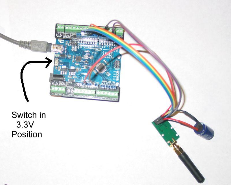
Here is the Arduino based hardware for this program. An Infiduino connected to a ElecHouse CC1101. I used a Screw Shield but its not really necessary as you can connect the CC1101 directly to the Infiduino. I also put a capacitor across the VCC/GND lines. I don't know if this is really necessary. Interconnections are detailed on the OOK Radio Support page.
I call the program RTCEngineE. Watch this video:
You can get my RTCEngineE (Infiduino/ElecHouse CC1101 version) program here <download ZIP file>. You also need to install my ElecHouse CC1101 libary as described on the OOK Radio Support page. Remember that you need an Arduino which can run on 3.3V (like the Infiduino) when you use the ElecHouse CC1101 radio.
Video 8
- Combining RTC, CTI TrainBrain and a RemoteTom sent me a video of his use of a handheld remote, my RTC program, my OOK Radio, and a program written by Mike Hewett using the CTI TrainBrain system. Tom was able to combine all three systems on his layout to control his trains.
Wiring for Good DCS Signal Distribution
Here is my power and DCS signal distribution wiring on my layout. With this scheme, I get Track Signals of 9 & 10 all around my layout. I use 3 of the 4 outputs from the TIU. Each of the three power about 1/3 of my layout. Someday, I'm going to rewire my layout and use all 4 outputs. The torriods around the red side of the power cables are used to monitor the current draw of each circuit. I used the DCS setup screen (of the Remote or of my RTC program) to change Variable Output 1 into a Fixed Output. Instead of the "Magic Light Bulb", I use "Engineered Filters" on each circuit. The filters are described on this web page: http://www.slsprr.net/technical/filter.htm The parts are: 1 - Metallized Polyester Film Capacitor - 0.1uF 100 volts 5% Mouser #: 80-R82EC3100DQ70J Mfr. #: R82EC3100DQ70J 1- Metal Film Resistor - ½ watt 221ohms 1% Mouser #: 71-CMF60221R00FHEK Mfr. #: CMF60221R00FHEK |
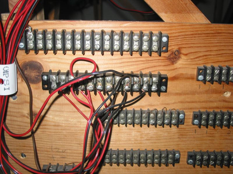 The layout is broken into about 30 blocks each consisting of about 10-15 pieces of Lionel postwar track. That makes each block 8'-12' long. I use a plastic insulating pin on the middle rail to electrically isolate the track block. Each output of the TIU goes to a terminal strip. At the terminal strip, separate circuits go off to each isolated block of track. |
 Here is another of the terminal strips. |
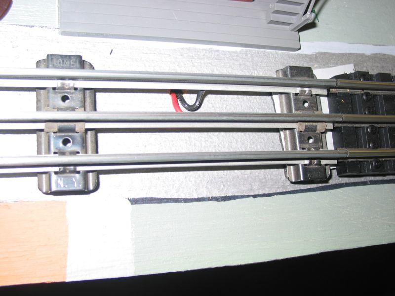 The wires from the terminal strips to to the track. I solder the wires to the underside of the each rail. I try to connect the wires as close as posible to the center of the block of track. |
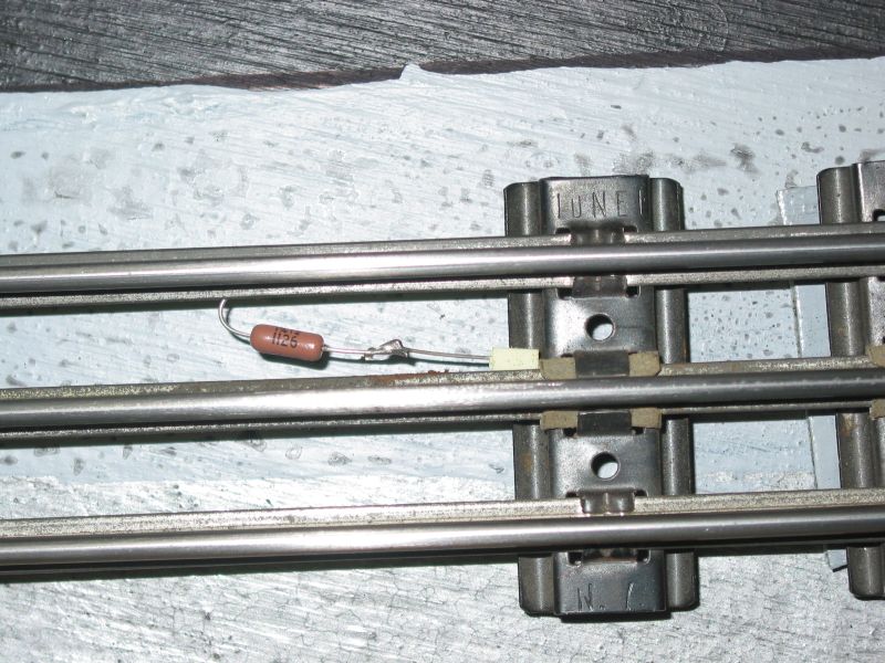 At one end of each block of track, I solder another filter between the outside and middle rails. So in total, I have 3 filters at the TIU and then 30 filters at the end of each block of track. |
At each terminal
block, I attach
a bidirectional TVS(Transient Voltage Suppressor) diode. I used the
diode recommended in posts on the OGR Forum.
I quote from this post by RTR12: "TVS Conventional - Digi-Key Part Number 1.5KE36CALFCT-ND - 1.5KE36CA - 36 volt, bi-directional - Sized for a PWZW when the whistle button is depressed. This peaks over 33 volts if the compensation winding is considered. (Part number recommended by many, explanation by Dale H) (Digi-Key part numbers from GRJ) TVS Command Control - Digi-Key Part Number 1.5KE33CALFCT-ND - 1.5KE33CA - 33 volt, bi-directional - Sized for the modern 18 volt bricks. The 18 volts peaks a bit over 25 volts. (HiRailers Unlimited & Independent HiRailers Group, explanation by Dale H) (Digi-Key part numbers derived from GRJ's above for 33 volt version) For the TVS, the
1.5KE36CA is most recommended here on the forum and also the most
widely used as it seems it would be suitable for either the modern
bricks or the transformers with whistle buttons."
|
 Here is a simple drawing that shows the connection to one block of track. |
One problem I've seen with sectional track is poor connection of the middle rail from one piece of track to another. This will affect your track signal and stop you from getting those 10's. As you assemble your track, throughly clean each rail pin and the inside of the connecting rail.
Screen recording performed with CamStudio.
