OOK Radio
Support for RTC
This Page last updated on
.
As I mentioned in the posts on the forum,
I am releasing these
programs and documentation under the GNU GENERAL PUBLIC
LICENSE Version 3 and GNU Free Documentation
License
Version 1.3. These licenses permit anyone to use the program and the
documentation to produce follow on programs as long as those programs
remain covered by the GNU licenses.
The Free
Software Foundation
web page talks about what "free software" means.
For more information, look on the Open Source Initiative
web site which includes a description of what Open
Source means
and their certification
of the GPL version 3.
Here is the copyright
notice
for those two licenses:
GNU GPL
This is part of the Remote Train Control Program for Windows
© Copyright 2015 by Mark DiVecchio
Remote Train Control is free software: you can redistribute it and/or
modify it under the terms of the GNU General Public License as
published by the Free Software Foundation, either version 3 of the
License, or (at your option) any later version.
Remote Train Control is distributed in the hope that it will be useful,
but WITHOUT ANY WARRANTY; without even the implied warranty of
MERCHANTABILITY or FITNESS FOR A PARTICULAR PURPOSE. See the
GNU
General Public License for more details.
You should have received a copy of the GNU General Public License along
with Remote Train Control. If not, see <http://www.gnu.org/licenses/>.
GNU FDL
This is part of the Remote Train Control Manual.
©
Copyright 2015 by Mark DiVecchio
Permission is granted to copy, distribute and/or modify this document
under the terms of the GNU Free Documentation License, Version 1.3 or
any later version published by the Free Software Foundation; with no
Invariant Sections, no Front-Cover Texts and no Back-Cover Texts. You
should have received a copy of the GNU Free Documentation License along
with Remote Train Control. If not, see <http://www.gnu.org/licenses/>.
PC Control of MTH Engines by Radio Connection to the TIU
Background
I've been working on understanding the interface between the Remote and
TIU for several years. I started with the work done by Mike Hewett
<mhewett737 yahoo.com>
in
about 2011. He investigated the wired connection (using a phone handset
cord) between the two. He figured out a lot of the interface. It was
RS-232 (using 0v and 3.3v levels). It was 9600 baud, 8 data bits, no
parity, 1 stop bit. He could see command packets going
between the Remote the TIU. He wrote software to capture those packets,
store them on a PC and send them to the TIU on request. yahoo.com>
in
about 2011. He investigated the wired connection (using a phone handset
cord) between the two. He figured out a lot of the interface. It was
RS-232 (using 0v and 3.3v levels). It was 9600 baud, 8 data bits, no
parity, 1 stop bit. He could see command packets going
between the Remote the TIU. He wrote software to capture those packets,
store them on a PC and send them to the TIU on request.
I took the work that Mike did and expanded on it. I developed a better
understanding of the command packet from the Remote and the response
packet from the TIU. I put all that I learned into a program called Remote Train Control.
I was still using a wired connection between the PC and the TIU. I
thought
that I could figure out how the radio connection worked.
Searches on Google developed a few leads:
1. Frequency requests to the FCC for Hand Held RF module and for Base
RF module:
This showed that the Remote transmitted on 916.5 MHz and the
TIU transmitted on 905.8 MHz
2. This I found this post on an SDR web site:
SDR-noob
needs help. Want to decode 9600bps OOK signal at 905.8MHz.
submitted 17
Nov 2014 by playaspec
Hi all.
I've been trying to reverse engineer the protocol used by a toy
train with little luck. Through a great deal of digging through Google,
I've discovered that the remote and the base communicate at 905.8MHz,
using OOK at 9600bps. I would like to snoop this protocol to bring the
train under computer control. Can anyone lend a hand?
The radio
chip in the receiver (and I assume the transmitter) is a TI
TRF6901 |
He never got any responses, except from me, and could not add to his
comment at the time. I don't know if he ever got to a solution because
I never heard from him again. But at least, if he
was right, I could search for OOK
and the TRF6901.
3. I needed to find out if anyone sold a radio board using the TRF6901.
Searching the Internet turned up nothing.
4. On the TI web page, the TRF6901 was listed as "NRND" - TI speak
for
"Not Recommended for New Designs". I downloaded the data sheet and saw
that the chip supported FSK (Frequency Shift Keying) and OOK (On-Off
Keying). So the
Remote and TIU probably spoke either FSK or OOK. I found this article: "I'm
OOK, You're OOK?" from Maxim. Another big hint was the
comment on the TI TRF6901 web page that stated: "Replaced by
CC1101".
I learned that OOK, which stands for "On-Off Keying" is a simple bit
serial protocol where the transmitter is just turned on and off based
on the "1" or "0" value of the bit being transmitted. Kind of like
Morse Code or what we hams call "CW" - Continuous Wave - transmission.
5. Since the TRF6901 was obsolete, maybe the CC1101
could be used. The data sheet said that it could do OOK. It was worth
investigating.
6. Now did anyone make a board using the CC1101? I found Erwan's Blog
which talks about connecting a CC1101 to a 3.3v Arduino variant called
the Infiduino. He used a board
from Elechouse
which contains the CC1101.
9. The Infiduino is
programmed using the standard Arduino IDE.
10. I learned how to program the CC1101 from scratch. I searched
the Internet and got little bits of help. I found a program called SmartRF
Studio 7 from TI which helps set the values needed for the
CC1101 configuration registers. Months of digging through the
CC1101 data sheet and test code for the Atmega328p MCU
finally led me to a
working receiver. Then a working transmitter. I called my
program "RTCModem". I could
communicate
between the PC and the TIU with my Remote
Train Control program. (note: this paragraph took about 5
months actual work.)
11. To program the CC1101, I took the code examples written by
Elechouse and
added
routines to implement OOK.
12. The protocol over the radio is just like the RS-232 TTL level wired
connection. You might think of it as inverted, though. When the RS-232
signal is a '1' or "Marking", the transmitter is off. In RS-232-land,
this is the idle state. With a radio, we want the transmitter to be off
when the connection is idle. This lets other remotes transmit and
control the TIU. It also saves our battery power. When the RS-232
signal is a '0' or "Spacing", the transmitter is on.
13. I found that both the Remote and the TIU require what I call a
"wakeup" signal be transmitted to them before data is transmitted. I'm
guessing that the receiver circuit needs a carrier signal for some
amount of time in order for it to lock onto the incoming signal. I
found by experimentation that a carrier on signal of about 2000
microseconds followed by a carrier off signal of about 600 microseconds
worked. Following this wakeup pulse, the next carrier on is
the
START bit of the first character of the packet of data. If you look at
the code, you can see where I do this.  Look at this link (on this page)
for more that I've learned about this wakeup pulse. Look at this link (on this page)
for more that I've learned about this wakeup pulse.
For details on the previous steps look at this
document.
|

|
Here are two articles that I wrote about RTC. They give simple
operating instructions and might be of use. The articles were
originally published in the TTOS Southern Pacific Division newsletter
"Daylighter" in March 2016:
Article
with screen shots and startup instructions
Article
with more technical description of the program's operation
You can also access
these videos on my YouTube
Channel.
Radio based
interface between the PC and TIU
My original work was done with a radio that is no longer available.
That radio consisted of of an Arduino-like processor using the
ATMega328
along
with a TI
CC1101
radio chip. Its programmed using the Arduino IDE.
 Jan 2019 - The original radio that I used is no longer available. Look
at the
solution using the Infiduino or Seeeduino (3.3v Arduino variants) and
the ElecHouse CC1101
radio.
Jan 2019 - The original radio that I used is no longer available. Look
at the
solution using the Infiduino or Seeeduino (3.3v Arduino variants) and
the ElecHouse CC1101
radio.
One thing the I will point out over and over (because I messed up here)
is that the TI CC1101 is a 3.3v part and can only connect to 3.3v
circuitry. A
plain Arduino is a 5v part and will NOT
directly connect
with the TI
CC1101 (safely). In the examples below, I used an Infiduino
which can be
switched to operate at 3.3v. And I show an example of a Seeeduino also
switched to operate at 3.3v.
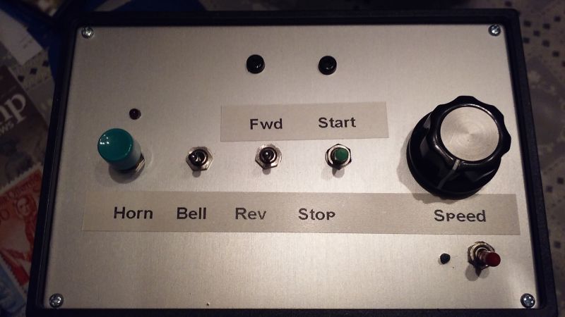
Retro Transformer
This is my first project using the original radio. Recorded 21 Sep
2015. Its only an example
of what could be done. I built it in a cardboard shipping box. Inside
are the radio, 2 AA batteries for power, a few switches, pushbuttons
and an old joystick (really just a fancy potentiometer). When you are
not transmitting, the board draws about 3ma. Great for battery
operation.
Jan 2019 - The original radio that I used is no longer available. Look
at the
solution using the Infiduino or Seeeduino (3.3v Arduino variants) and
the ElecHouse CC1101
radio.
Take a look:
Image loading....
First Project -
a Retro Transformer
This box performs just a sub-set of the functions performed by the
remote. It is hardcoded to control one engine and communicate
with one TIU. But I could see a controller built with large buttons,
something really kid friendly. Or how about a track activation device
that sounds the whistle/horn automatically when the engine approaches a
grade crossing. Maybe even an automatic speed control as the engine is
approaching a station. It can be extended to control accessories and
switches. Mike Hewett has developed a scheme with which he can identify
the position of each engine on the layout. With that, you can develop a
system that performs different functions depending on which engine is
coming into town. Maybe routes them onto different sidings or to
different industries (by commanding the AIU).
You can
get the RetroXFMRE (ElectHouse CC1101 version) program here
<download ZIP
file>.
See below for instructions on how to use the Arduino IDE to compile
and download these programs. Each also requires a support library.
Each of these ZIP files contain a circuit schematic of how I connected
up the switches, pushbuttons and pot. The schematic is for the original
radio but you can translate the pin numbers to match
the Infiduino/Seeeduino used in the Elechouse CC1101 version.
You need to
download the free
program KiCad EDA to view these files. Look here: http://kicad-pcb.org/
Below, you can see an implementation of RetroXFMRE
by Ray.
Developer's
note: If you are interested in learning how to
use the Infiduino/Seeeduino to control your trains,
this
RetroXFMR is the best place to start. Look at the code to learn
how to take a command and add all of the bytes around it to
build
a packet that can just be sent over the radio. Once you understand
this, you can use my routines to build up and send your own commands.
Infiduino
with
Elechouse
CC1101
Earlier in this page, I mentioned Erwan's Blog
which talks about connecting a CC1101 to an Arduino. He used a radio
board
from Elechouse
which
contains the CC1101 connected using the Arduino's SPI interface.
First
let me point out (again!) that the maximum
voltage on any pin of the
CC1101 is 3.3v. You cannot
use a regular Arduino UNO but
you have to use
one that operates at 3.3v. There are many of these available. I used a
version called an Infiduino. It has a switch for either 3.3v or 5v
operation. I got it on eBay.
So I thought that I could port my RTCModem program to an Infiduino/Elechouse
CC1101 setup. The time I spent learning about the
CC1101 in the original radio should be directly useable. It was. The
developers of the
Elechouse CC1101 had written code for the Arduino to communicate with
the CC1101. Since I now understood how all this worked, it was easy to
port the code. I added an "E" to the program name to indicate that it
is the Elechouse CC1101 port - "RTCModemE".
Click
here for a source for
the Elechouse 915MHz CC1101 Wireless Module (directly from
Elechouse). The page shows this module as "RF1100SE" but the boards
that I received are marked "RF1101SE-V3.1". The web page claims that
this board is designed specifically for operation in the 915MHz band.
As of Jun 2019, it was $18.90 + shipping. Elechouse ships from a US
address.
Most of the boards on eBay are V2 and may not work at 915MHz. They
appear to be 433 MHz boards but you never
know. They are pretty cheap so there is not much to lose if you try
them.
I've found three other sources for TI CC1101 radio boards that work
with RTC:
Chengdu
Ebyte Electronic Technology Co.Ltd
has a board E07-915MS10. This eByte board will require some soldering
of wires and an antenna (3 inch wire). You can find it by
searching
eBay.
These boards are really cheap, in Jun of 2019, they were $3.70 each +
shipping .
Now
being sold as "Goupchn
SPI RF Transceiver Module CC1101 915MHz SPI E07-915MS10" and as of Oct
2021, they are $6.59 with free shipping. They come over on a slow boat,
my order took almost 5 weeks. See below for the wiring
diagram.
These boards have become hard to find. It looks like they are
available on
aliexpress
at this link. Shown for $3.00 + $3.95 shipping.
This
board on
eBay is marked "RF1100SE" but like the Elechouse board, I
actually
received a board marked "RF1101SE-V3.1". This board looks
exactly
like the Elechouse board except that it has a small wire antenna
instead of the black SMA antenna. You wire it up with the same
connections as the Elechouse CC1101 radio (see beow). As of June 2019,
it was $8.71 + free
shipping. Cost was less if you bought more than one. Worked just fine.
Like the shipment from eByte, it took almost five weeks to arrive via
"SpeedPAK" from Hong Kong. I get the feeling that this is a knock-off
of the Elechouse board.
I
cannot find this board on eBay any more.
This board
on eBay
uses an eByte module, E07900M10S. the module and the board are made
specifically for 915 MHz.The pinouts are different than the Elechouse
board but you should be able to match up the pin names with the pin
names shown in the Elechouse wiring diagram. These boards are made by a
guy who runs an
O
Scale Dead Rail web page. They were $9.99 as of December 2024.
Here is an
eBay
search for
the CC1101 radio. If the link does not work anymore, use this
search "915MHZ wireless module/CC1101 wireless data".
It is
very
important that the radio be advertised as "915MHz".
If it says "315/433/868/91
5MHZ" or just "433MHZ",
it probably will not work with RTC.
Here are some other links:
Search
eBay for the Infiduino.
Search
eBay for the jumper cables.
These are called Dupont Cables. They are used to interconnect the
Infiduino and the ElecHouse CC1101 radio. You will need male to female
jumper cables.
Elechouse
page for the CC1101 Radio.
In the spring of 2020, the Infiduino has, for some reason, become very
difficult to find. Mike Hewett, one of the RTC users, found a Seeeduino
variant manufactured by Seeed. A little further down this page, there
are a couple of photos of Mike's implementation.
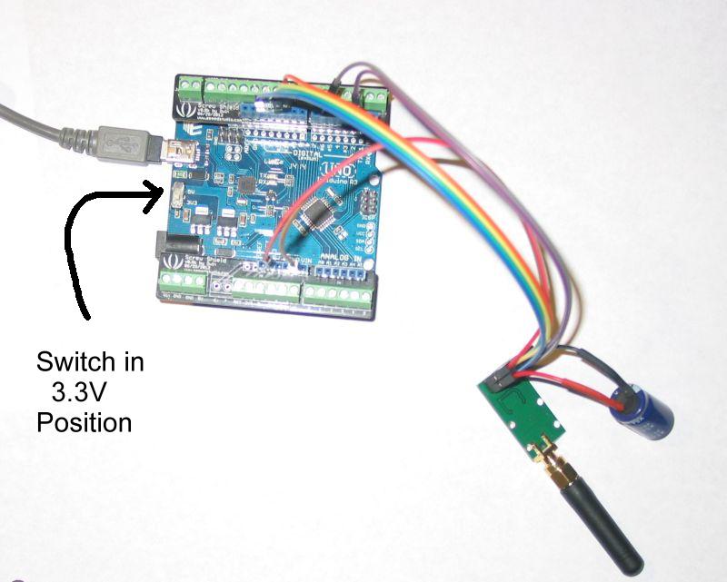
Here is a photo of my Infiduino jumpered over to an
Elechouse CC1101
(using a Screw Shield - but the Screw Shield is not really needed - you
can connect the jumpers directly to the Infiduino). I
also added a 100uF electrolytic decoupling capacitor arcross the power
pins on the
CC1101. I don't really know if this is needed or not - seems to work
fine with it and without it.
This is solderless solution..... Source for jumpers - MPJA.com
.
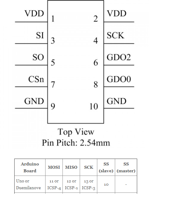
Here are the pinouts of the Elechouse CC1101 board using the SPI
interface. This drawing is
linked from Erwan's
blog.
Note that this is the top or component side
view of the CC1101 radio, the pins themselves
actually stick out on the other side of the board.
It seems that on
these boards, pins 1 & 2 are labeled "VCC" instead of "VDD".
VDD is
typically 3.3v.
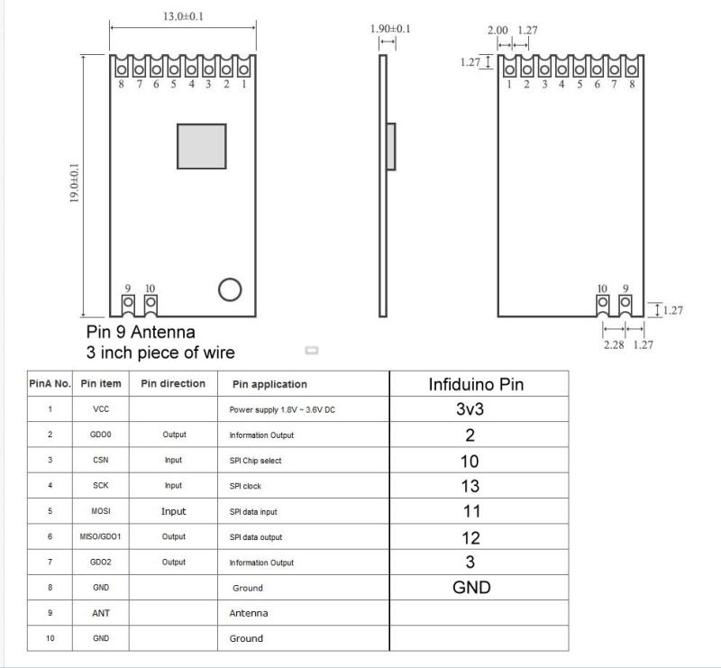
Here is a drawing that shows how to interconnect the two devices. This
drawing is linked from Erwan's
blog with one modification. My OOK implementation requires
one more interconnection than Erwan used, from Infiduino 03 to CC1101
GDO2 / 6.
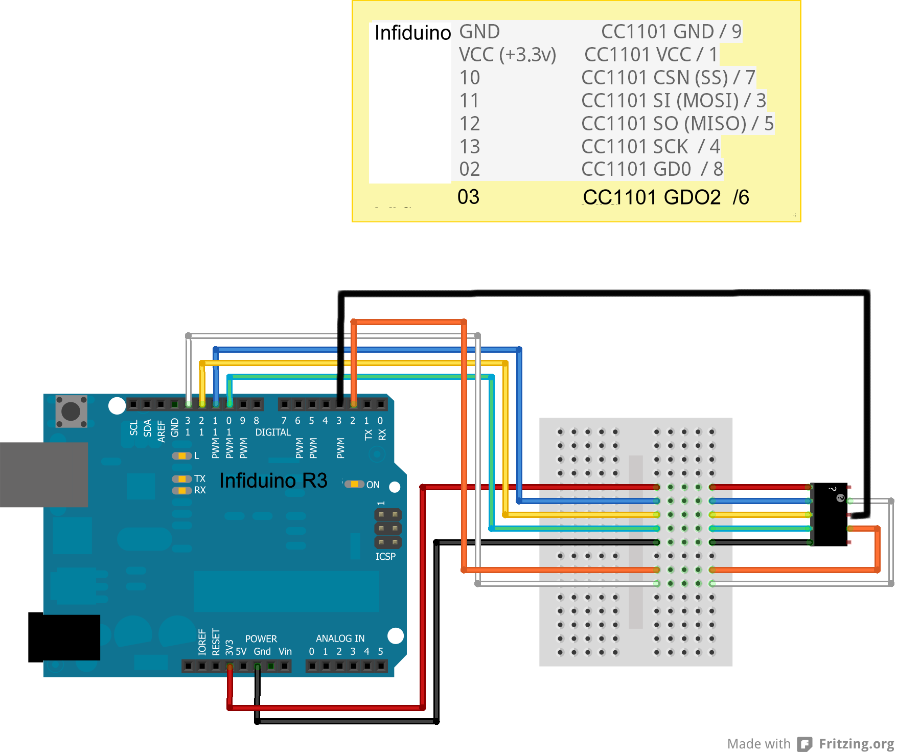
The black square is the CC1101 radio. This is a odd diagram for the
radio and can be confusing.
The 10 pins on the black square are the 10 pins on the radio board. The
upper left is pin 1, the upper right is pin 2 and so on.
Remember that this view is from the top or component side of the radio
board.
The pins actually stick out from the bottom or solder side of the board.
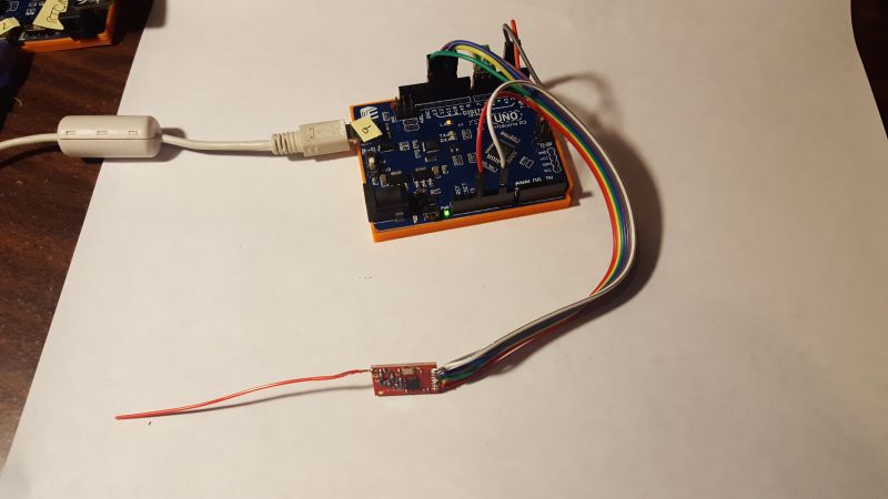
Here is the wiring
for the eByte super cheap CC1101 radio.
Here is the eByte radio connected to an Infiduino
Seeeduino
based radio.
Mike Hewett, one of the RTC users, found a Seeeduino
variant manufactured by Seeed. It has a switch on it to change the
operating voltage to 3.3v.
NOTE: the radio described in the next paragraph seems to have
disappeared from eBay. You will have buy the radio from Elechouse.
Here is an eBay
search
for
the CC1101 radio that Mike used. If the link does not work anymore, use
this
search "915MHZ wireless module/CC1101 wireless data ". It
is very
important that the radio be advertised as "915MHz". These
radios have
an antenna system designed for the correct frequency. The radios
advertised as "315-433-868-915MHZ" have antennas systems designed for
433MHz and will not work as well in this application. This board on
eBay is marked "RF1100SE" but like the Elechouse board, I actually
received a board marked "RF1101SE-V3.1". This board looks
exactly
like the Elechouse board except that it has a small wire antenna
instead of the black SMA antenna. You wire it up with the same
connections as the Elechouse CC1101 radio (see beow). As of June 2019,
it was $8.71 + free
shipping. Cost was less if you bought more than one. Worked just fine.
Like the shipment from eByte, it took almost five weeks to arrive via
"SpeedPAK" from Hong Kong. I get the feeling that this is a knock-off
of the Elechouse board.
Chengdu
Ebyte Electronic Technology Co.Ltd
has a board E07-915MS10. This eByte board will require some soldering
of wires and an antenna (3 inch wire). You can find it by searching
eBay.
These boards are really cheap, in Jun of 2019, they were $3.70 each +
shipping . Now
being sold as "Goupchn
SPI RF Transceiver Module CC1101 915MHz SPI E07-915MS10" and as of Oct
2021, they are $6.59 with free shipping. They come over on a slow boat,
my order took almost 5 weeks. See above for the wiring
diagram.
These boards have become hard to find. It looks like they are
available on aliexpress
at this link. Shown for $3.00 + $3.95 shipping.
Click
here for a source for
the Elechouse 915MHz CC1101 Wireless Module (directly from
Elechouse). The page shows this module as "RF1100SE" but the boards
that I received are marked "RF1101SE-V3.1". The web page claims that
this board is designed specifically for operation in the 915MHz band.
As of Jun 2019, it was $18.90 + shipping. Elechouse ships from a US
address. This board is more expensive and possibility higher quality
than the knock-off board but both boards seem to work fine.
Mike wrote: "I used
double backed adhesive tape and wire wrapped to header pins pushed into
the seeeduino board mounted female headers"
Using a 5v Arduino instead of 3.3v Infiduino/Seeeduino
It is possible to use a regular 5v Arduino for this application. The
Arduino has a 3.3v voltage regulator on board and that voltage pin can
be used to power the radio. The Arduino's input pins can (usually)
accept the lower 3.3v signals from the radio (for the MOSI,
the
GD02 and the GD03 pins). Arduino output pins, though, would be 5v
signals and cannot be directly connected to the radio (for the CSN(SS),
the SCK, and the MISO pins). These three signals must have their
voltage lowered to 3.3v before connecting to the radio.
You can do this two ways that I know of.
- Use a level converter chip.
There are chips which take in a signal at 5v levels and convert them to
3.3v. Many possibilies available. Look at these web pages for options:
https://codeandlife.com/2012/04/06/level-shifting-101/
or https://randomnerdtutorials.com/how-to-level-shift-5v-to-3-3v/
.
Often called a poor man's level converter, put a 1K-5.2Kohm reisistor
in the three signals (the CSN(SS), the SCK, and the MISO pins)
from the Arduino to the radio. This resistor will just provide about a
2 volt drop to lower the voltage but still might damage the radio. This
is not an ideal solution as the signal waveform will get distorted
somewhat. But,well, this is not rocket science.
Compiling the Modem Program
You compile the RTCModemE program using the standard Arduino IDE and
the standard Arduino libaries along with my "CC1101E" library as
described below.
Install the Arduino IDE. When I wrote this, 1.6.5-r2 was the lastest
version. Get it here: https://www.arduino.cc/en/Main/Software
Make sure that "Arduino AVR Boards Built-In" is installed. I'm using
version 1.6.8.
| Note: in Aug of 2016, one of my users wrote: "I used Arduino IDE 1.6.8 and
AVR Board
1.6.13
(instead of
1.6.8) - For some reason, AVR Board 1.6.8 did not include TimerOne.
I was getting include errors initially looking for
TimerOne.h.
I went and downloaded TimerOne from GitHub, but also the
switch
to 1.6.13 might have helped." |
Detailed installation instructions are here: https://www.arduino.cc/en/Guide/HomePage.
Make sure that the Arduino AVR Libraries (I'm using version 1.6.8) are
loaded. https://www.arduino.cc/en/Guide/Libraries
Newer versions of the IDE and AVR Libraries should work but
I've
not tried them.
In your Arduino Sketch folder, create a folder named "RTCModemE" and
put
these two files in it:
RTCModemE.ino
RTCModemE.h
You can get my RTCModemE (Elechouse CC1101 version) program here
<download ZIP file>.
This library is my implementation of OOK protocol on the Infiduino with
the Elechouse CC1101. You can get the my CC1101E_OOK library (Version
1.0.4) here
<download ZIP file>.
In the zip archive, look for the folder CC1101E. Move that folder and
its contents into your Arduino libraries folder - on my Win 7 computer,
its a folder named:
C:\Users\<user>\Documents\Arduino\libraries.
In your local Arduino Library folder, create a folder named "CC1101E"
and put the CC1101E_OOK library files in it.
You might need the USB VCP drivers from the FTDI web site.
This is only if the drivers do not load automatically.
Get the latest version for Win 7, Win 8 and Win 10. At the time of
this writing, that is version 2.10.0.0 (dated 1/27/2014). Get the
older,
no longer supported, version 2.8.30 (dated 7/12/2013) for Win XP (still
works fine). NOTE
- this version for XP seems to be gone from the FTDI web site - in its
place, get the latest version 2.08.24 dated 4/13/2012.
Install the "Arduino AVR Boards" support as follows:
1. Start the Arduino IDE.
2. Click on "Tools->Board->Boards Manager"
and scroll
down the window until you find the "Arduino AVR Boards" entry. Then
click on [INSTALL] -- unless its already installed.
3. Click on "Tools->Board" and select the
"Arduino Uno" board. NOTE: you can use any Arduino board, does not have
to be a Uno.
4. Connect the Arduino to the PC into a USB port. Drivers for the board
should install. Note which COM port
that it configured as.
5. Select that COM port on the "Tools->Port"
menu item.
6. Open the "File->Open"
menu and select the RTCModemE.ino file
7. Click on "Sketch->Upload"
to complile and upload the code into the Arduino.
8. Start your program, might be RTC or one of Mike's programs. Select
the
correct COM port. Turn on your TIU, press CONNECT, READ, and then
STARTUP and run an engine.
Email me if you have questions or clarifications (or if your setup
actually worked!). email : markd@silogic.com
---------------------------------------------------------------------------------
Notes::
1. Requires TimerOne which is installed when the Arduino AVR Boards
support is
installed.
2. Requires SoftwareSerial which is installed when the Arduino
AVR Boards support is
installed. SoftwareSerial inverts the data in both directions. Required
so that
when the serial data is "1", the transmitter is off and when its a "0",
the transmitter is on. RS-232 Marking state ("1") is its idle state and
we don't want the transmitter on when the channel is idle.
I had to make a few patches to the
Software Serial
routines
as received with the Arduino AVR library. If you download the
Board Mangaer files for the "Arduino AVR Boards" boards, you will have
to make these patches. They increase the buffer size to insure that the
173 byte
packet from the TIU can be received without the possibility of overflow.
SoftwareSerial.h
Increase the buffer size from 64 bytes to 256 bytes:
#define _SS_MAX_RX_BUFF 256 // RX buffer size MCD was 64 (apparently this must be a power of 2)
Change the buffer pointers from 8 bit to 16 bit:
static volatile uint16_t _receive_buffer_tail; // MCD was uint8_t
static volatile uint16_t _receive_buffer_head; // MCD was uint8_t
SoftwareSerial.cpp
Change the buffer pointer from 8 bit to 16 bit:
volatile uint16_t SoftwareSerial::_receive_buffer_tail = 0; // MCD was uint8_t
volatile uint16_t SoftwareSerial::_receive_buffer_head = 0; // MCD was uint8_t
|
3. I get these two warning messages when I compile. They don't seem to
have any effect on the operation of the sketch.
...\SoftwareSerial.cpp:375:6: warning: always_inline function might not
be inlinable [-Wattributes]
void SoftwareSerial::setRxIntMsk(bool enable)
^
...\SoftwareSerial.cpp:121:6: warning: always_inline function might not
be inlinable [-Wattributes]
void SoftwareSerial::recv()
^ |
Adafruit Feather 32U4 Based Radio
Paul Reynolds, who is working on his own version of radio control,
alerted me to a radio which I had not seen before. Its from Adafruit
and is
called the "Adafruit Feather 32u4 RFM69HCW Packet Radio - 868 or 915
MHz". Like the other radios that I've used, it is much, much more
capable than I need and handles very sophisticated transmission
protocols. We only
need OOK to talk to the TIU and when I looked up the radio chip used,
the SEMTECH SX1231 Low Power Integrated UHF Transciever, the specs said
it could handle OOK.
Here is a photo of the radio:
I was able to take the RadioHead library and make it work for me using
OOK. So this is another good radio to use for the RTC program. It is
nice in that is single board and costs about $25 but it is not a
solderless solution.
Because the USB is built into the Feather 32U4, instead of an external
chip
as on a regular Arduino, it requires that DTR be high otherwise the
Feather will never send anything to the PC. The Arduino IDE does this
automatically if you use the builtin terminal. If you use a standalone
terminal, you will have to set it to turn on DTR. I had to modify the
RTC program with a new setup option [x]
DTR Always on - added in
version 4.3.2 of RTC. You must set this before connecting to the TIU.
The setting is remembered so you only need to set it once.
Then as you can see in the photo above, a jumper is required on the
Feather. This jumper is to connect the DATA02 pin of the radio to pin
D9 of the RFM69HCW. The DATA02 pin is used to both send and receive
serial data from the radio for the OOK function. Solder a
jumper
between pin 2 of the radio to pin D9 of 32U4. Please do a better job of
soldering than I did :-(.
I also soldered on a spring antenna that I bought along with the radio
from Adafruit. You can also use a simple 3 inch piece of wire.
Here are the sketches I have so far and the modified library. I've not
used these for any long term testing so you might find a bug or two. If
you do, let me know and I will (hopefully) fix them.
RTCModemF_v1.0.1
- Connects the
RTC program to the TIU. Includes the "hex" file which can be uploaded
into the Feather using the XLoader program (see just below).
RTCSnoopF_v1.0.0
- Monitors
radio communications between the Remote/RTC and the TIU. Displays the
packets heard on the air. Includes the "hex" file which can be uploaded
into the Feather using the XLoader program (see just below).
RadioHead_OOK -
The RadioHead library modified to support OOK protocol. You will need
this if you want to recompile the Feather sketches.
ATMEGA1284P based Radio - Moteino
+ RFM69HCW
Jeff Lefstin saw the work that I did with the Adafruit Feather 32U4 and
RFM69HCW radio. He took my port of RTCModem to that board and ported it
to a Moteino Mega. The Moteino combines an ATMEGA 1284P with the
RFM69HCW radio. He developed a interface between the Lionel Legacy
remote and
the MTH TIU. That is - being able to control DCS engines with the
Legacy remote. Here is what he wrote (also appears on this
OGR Forum posting):
With the impending demise of the MTH DCS remote, I
wanted to explore
the possibility of controlling PS2 and PS3 trains with the Lionel
Legacy remote.
While
it’s possible to read commands from the TMCC or Legacy base
serial
port, doing so may require additional hardware such as a SER2 module.
Moreover, because the TMCC and Legacy command bases use earth ground
as the reference for the serial bus, a separate power supply or
optical isolation is necessary to avoid shorting layout common to
earth ground (which may interfere with the TMCC signal). Instead,
this system plugs into the Lionel LCS PDI bus, which provides a 12v
power line.
Basic
Hardware:
Mark
had demonstrated communication with the TIU using an Adafruit
Feather, which combines an Atmega 32U4 and an RFM69HCW radio module.
I used a Moteino
Mega, which is a similar module with an Atmega 1284p. The Moteino is
easier to power with an external supply, and had the pins I needed
for serial communication available.
There
are two versions of the Mega: one
with a built-in USB converter for the
first Serial
port, and one
without, which requires an FTDI-type
USB to serial
converter to program the module. Either will work for this
application, but be sure to get the version with the RFM69HCW
–
868/915 Mhz tranceiver. Instructions on installing the Moteino board
files in your Arduino IDE are here;
you do not need to install the Moteino libraries. NOTE:
If you are using the non-USB
version, DO NOT connect your
FTDI adapter while the module is powered from the LCS bus –
you
will feed 12v into your adapter and USB port!
There
are two jumpers on the back of the Mega that allow connections
between the RFM69HCW and Moteino that are not enabled by default: one
between D3 and the RFM69’s reset, and another between D21 and
DIO2
on the RFM69. Both of these jumpers should be bridged with solder as
shown below:
Connection
to the Legacy LCS
The
PDI bus uses RS-232 at 115200 baud to transmit commands between the
Legacy base and LCS modules. This presented a problem, because
Mark’s
original implementation used the Arduino SoftwareSerial library at
9600 baud to communicate with the RFM69. The SoftwareSerial library
blocks while outputting to the serial port, and at 9600 baud it may
block long enough to miss characters coming in from the PDI bus on
the hardware port Serial1. (The RFM69 uses inverted signaling to
transmit and receive data on DIO2, so we either have to use a
software serial port that supports inverted signaling, or implement a
hardware inverter).
I
used the AltSoftSerial
library instead, which provides non-blocking write operations using
the Arudino’s timer interrupts. However, AltSoftSerial
doesn’t
support inverted signaling, so I modified the library to provide an
option for inverted signaling like SoftwareSerial.
(“InvAltSoftSerial”). The library transmits and
receives on pins
13 and 14, which are the output compare and input capture pins for
the 1284’s 16-bit timer. Since the RFM69 transmits and
receives
serial data on the same pin (DIO2), I tied pins 13 and 14 together
and connected them to DIO2 via Moteino D21 with a 100 ohm resistor
(to limit current in case the RFM69 and 1284 ever try to drive the
line in opposite directions).
Connecting
to the Lionel LCS is simple: the RS-232 signal from the PSI bus is
fed into an ADM3202 chip (which is equivalent to a MAX3232). The
ADM3202 converts the RS-232 signals to TTL 3.3v signals that are read
by the 1284’s second hardware serial port (Serial1).
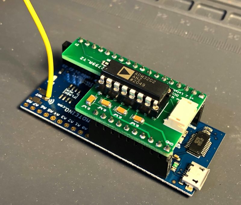
I
created a basic PCB that can be plugged on top of the Moteino Mega
with female headers. A JST header is provided to plug in the PDI
cable from the Legacy LCS bus. This version uses 1206 surface-mount
capacitors and resistors, but I designed a version that uses
through-hole components as well:
Software
The
Legacy Command Base will echo any TMCC or Legacy commands it receives
from the CAB-2 onto the LCS PDI bus. The Moteino reads the packets
coming in on the PDI bus, and parses any TMCC or Legacy 3-byte
commands coming from the Command Base. (Legacy also has more
“multi-word” commands used for more complex
lighting and dialog
effects, but the current version of the software doesn’t
attempt to
parse them.)
The
demonstration sketch shows two simple uses of the CAB-2 to control a
DCS engine: controlling the speed of an engine, and opening the front
and rear couplers. Those are simple conversions of Legacy commands to
their DCS equivalents.
Providing
full control of DCS engines with the Legacy remote will require
mapping many more Legacy commands to a corresponding DCS command
sequence – and some of them, like sound commands, do not have
a
simple DCS equivalent. That project is not something I have the
appetite to take on, so my hope that other people will be inspired to
take the system further!
If
you are interested, the
attached ZIP file contains a schematic and
Gerber files for the PCB, the demonstration sketch, and the
InvAltSoftSerial and other libraries used by the sketch. |
So this concept still needs a lot of work. Mostly mapping the Legacy
commands to the DCS commands.
XLoader - Uploading
code images to
the Infiduino without having to install the IDE and compile
the code
Here is a way to upload a precompiled binary image of these
programs without having to load the Arduino IDE and compiling the code.
The precompiled code is available below for the
Infiduino/Elechouse CC1101.
This procedure is based on Xloader by Geir
Lunde:
-------------------------------------------------------------------------------
Copyright (c) 2012, Geir Lunde
All rights reserved.
THIS SOFTWARE IS PROVIDED BY THE COPYRIGHT HOLDERS AND CONTRIBUTORS "AS
IS" AND ANY EXPRESS OR IMPLIED WARRANTIES, INCLUDING, BUT NOT LIMITED
TO, THE IMPLIED WARRANTIES OF MERCHANTABILITY AND FITNESS FOR A
PARTICULAR PURPOSE ARE DISCLAIMED. IN NO EVENT SHALL <COPYRIGHT
HOLDER> BE LIABLE FOR ANY DIRECT, INDIRECT, INCIDENTAL, SPECIAL,
EXEMPLARY, OR CONSEQUENTIAL DAMAGES (INCLUDING, BUT NOT LIMITED TO,
PROCUREMENT OF SUBSTITUTE GOODS OR SERVICES; LOSS OF USE, DATA, OR
PROFITS; OR BUSINESS INTERRUPTION) HOWEVER CAUSED AND ON ANY THEORY OF
LIABILITY, WHETHER IN CONTRACT, STRICT LIABILITY, OR TORT (INCLUDING
NEGLIGENCE OR OTHERWISE) ARISING IN ANY WAY OUT OF THE USE OF THIS
SOFTWARE, EVEN IF ADVISED OF THE POSSIBILITY OF SUCH DAMAGE.
https://github.com/binaryupdates/xLoader
-------------------------------------------------------------------------------
I have updated Geir's software with programs and files compiled with
v1.6.5 of the Arduino IDE. The zip file contains a program which will
load a hex file into an
Arduino based board. Make a folder (maybe called XLoader) and extract
all of the files in the ZIP into that folder.
The ZIP file below conatins the XLoader program and all of the *.hex
files.
To run click on XLoader.exe
Choose the Hex file to load.
Choose the Device.
Choose the COM port.
The Baud rate will be set automatically.
Click on "Upload".
-------------
My RTC files included were the latest
versions of the programs at the time. The compliled output files are
named <program>.cpp.hex
Remember than any system that uses the Elechouse CC1101 radio requires
an Arduino implementation that operates at 3.3V (such as the Infiduino
or Seeeduino).
RTCModemE -
provides radio communications between the PC and the TIU for the
Remote
Train Control (RTC) program as described
earlier
on this page. The receiver bandwidth is set to 162.5 kHz.
This
bandwidth has worked for me using Rev I, Rev I3A and Rev L TIU.
RTCModemF -
Adafruit Feather 32U4 version of RTCModemE.
RetroXFMRE -
My simple implementation of a toy train transformer as described
earlier on this page.
RTCEngineE -
A program which
emulates an Engine connected to a TIU. It outputs the commands it
receives and responses that it sends to the Arduino IDE Serial Monitor
Port. Look at Technical Video 7 at
http://www.silogic.com/trains/Technical%20Videos.html
RTCSnoopE -
A program which
monitors the radio communcations between the Remote and TIU and logs
the packets to PC using the Arduino IDE Serial Monitor (or any terminal
emulator). To decode these
packets copy/paste them into RTC's TIU buffer using RTC's debug mode.
Then from the TIU Buffer's context menu, click on "Decode Strings in
TIU Buffer". This will put the decoded strings into the CRC Buffer. You
can copy and paste or save them from there.
You can leave comments in the logged packets to reminder of what button
you just pushed. In the serial monitor just type a note to yourself and
press [Send]. A note could be something like "Press the Startup button".
If you use the XLoader downloaded version, you can use any terminal
emulator to capture the packets. I've used Termite:
http://www.compuphase.com/software_termite.htm with success.
Set the baud rate to 57600.
RTCSnoopF -
Adafruit Feather 32U4 version of RTCSnoopE.
TwoEngineE -
A program which
runs two engines around and around on your layout. Requires a Sharp
GP2Y0A21YK infrared (IR) detector, a pushbutton and an LED.
Written only for an Infiduino and an Elechouse CC1101 radio. Requires
DistanceGP2Y0A21YK.h and TimerOne.h. Look at
Technical Video 6 at
http://www.silogic.com/trains/Technical%20Videos.html
Fast_Clock_Master
Fast_Clock_Slave
Model railroad fast clock
master and slave.
Requires TM1637.h, TimerOne.h and EEPROM.h. Hardware
requirements
spelled out in the source code file.
Fast_Clock_Master.cpp.hex
Fast_Clock_Slave.cpp.hex
You can download the XLoader program and compiled binary versions of my
programs <download
ZIP file>.
There have been some comments that the XLoader.exe program in the ZIP
file has a virus but I checked it with Malwarebytes and found none. I
have run it on my computer with no apparent problem. Requires dotNET
v4.0.30319 (at least on WinXP). On my Win7 computer, I have dotNET
version 4.6.1. Win10 & 11 include dotNET 4.6.1 automatically.
NOTE: for
those of you old-timers who still use the original OOK radio (the panStamp), compiled
binary versions of those sketches are included in the ZIP file above.
They are RTCModem.cpp.hex and TBModem.cpp.hex.
You can download the source code for all of these programs here <download ZIP file>.
Mar 2016 Demo
of RTC
at the TTOS SP Meet in Anaheim, CA
Here is a video taken at the March 2016 meet of the Toy Train Operating
Society in Anaheim. Photos and videos taken by one of the RTC users,
Tom Niemi. It shows my simple demo layout and some of the portable
layouts at the meet. I didn't bring my
portable to this meet.
Image loading....
Examples
of Implementations by Users of RTC
Ray was the first person to report success at installing the Arduino
IDE, buying an Infiduino and Elechouse CC1101 radio, compiling
RTCModemE and actually running trains! Here are a few photos that he
sent me:

Here is the Infiduino wired to an Elechouse CC1101
Ray, is this a real breadboard? |
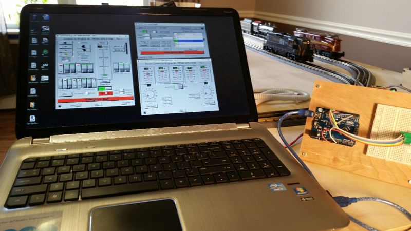
Ray's PC running RTC |

RTC Screens |
Ray then went on to build the Retro Transformer. Here is a video that
he sent me:
Image loading....
In 2017, Ray
built an upgraded and repackaged version of the Retro Transformer.
From: "Ray Leiter"
Subject: RetroXFMR finally done
Date sent: Fri, 7 Jul 2017 19:34:45 -0400
Mark;
Here is a
picture of the Retro Transformer finally completed.
I hate to admit
it but the
crazy thing was working all along. The reason it appeared to not work
was because I wired the speed pot backwards. When the knob was turned
fully CCW (which would normally be 0 smph), it was actually full speed
and as you well know, you can’t do a startup in that
condition.
I discovered it
after I made it work without any controls. I since then wired it
correctly and it now works as it did before.
On another
matter; I am
still waiting on my parts order from Futurlec. I need the parts to
build Adrian’s UHF Block Detector circuit. I don’t
think
I’ll ever order from them again.
Ray |
 |
 |
 |
Wakeup Pulse
With the help of Kevin Rice and his Software Defined Radio (SDR), I've
been able to learn more about the wakeup pulse.
I found that both the Remote and the TIU require what I call a
"wakeup" signal be transmitted to them before data is transmitted. I'm
guessing that the receiver circuit needs a carrier signal for some
amount of time in order for it to lock onto the incoming signal. I
found by experimentation that a carrier on signal of about 2000
microseconds followed by a carrier off signal of about 600 microseconds
worked. Following this wakeup pulse, the next carrier on is
the
START bit of the first character of the packet of data.
When I first discovered this pulse, my knowledge and equipment was
pretty primitive. I estimated the pulse to be about
2000 µsec in length with a quiet time of about 600
µsec before the data began.
Now Kevin has helped me better define the pulse. He used an SDR to
actually listen to and record the transmission from a Remote. He
captured the signal into a WAV file and emailed it to me. I loaded it
into Audacity. Here is a screen grab:
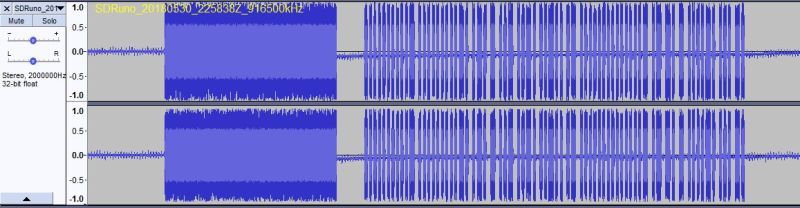
If I had this image a few years ago when I was first experimenting with
OOK, it would have made my work a lot easier.
This is a transmission from the Remote of a "bell on" command. The
wakeup pulse is clearly visible on the left. Then you can see the quiet
time before the first start bit of the first byte of the command. I
wrote this short description a while ago:
When either the TIU or Remote begin a transmission,
they
output a carrier for some period of time (1000-2000 microseconds), then
carrier off for about 500 microseconds. I call this a "wakeup pulse".
It might be there to let the Phase Locked Loop in the radio lock onto
the carrier.
Then when the carrier goes on the next time, that is the beginning of
the start bit of the simulated RS-232 character. The carrier on
indicates a "0" bit and the carrier off indicates a "1" bit.
To the radio, the idle condition is carrier off or "1" condition thus
saving the batteries. In the old time world of baudot radio
transmission, a "1" was called a "mark" and a "0" was called a "space".
So an idle line was "marking".
At 9600 baud, each bit occupies about 104 microseconds.The bits in each
data byte are transmitted LSB first.
Look on my
RTC web page and in my code for "4b8b" and Morton encoding
which are both used on the data.
These encodings take the 8 bit data byte, convert it to 16 bits and
then encode the data in such a way that there is never more than 2 "1"s
or 2 "0"s in a row in the transmitted signal. |
Now I can measure the pulse using Audacity. The carrier comes
on
for 8.0 ms which is the "wakeup pulse". Then the carrier goes off for
1.3 ms. (In my OOK code, I use 2.0 ms and 0.6 ms which seem to
work fine.) Then the carrier starts going on and off with the data.
Each carrier on-time represents a "0" bit and off-time represents a
"1". Each byte of data consists of a "0" start bit, followed by 8 bits
of the actual data (LSB first), followed by a "1" stop bit. This
repeats for each byte of data. Since the radio communicates at 9600
baud, each bit is 104 microseconds long. I can also measure that from
the wav file.
Of course, I can see all of this only because I spent untold number of
hours analyzing the signal with the CC1101 based radio.
I used Embarcadero
C++ Builder v10.1 Berlin to compile the program.
I used Audacity
and WavePad
to try different decodes on the ".mth" file.
I used hex editor HxD
in understanding the format of the sound file and in editing the sound
file.
I used SOX
to understand and convert audio files from one format to another.
I use Lame
to convert clips to mp3 format.
Screen recording
performed with CamStudio.
and with Icecream
Screen Recorder.
This site prepared and maintained by Mark DiVecchio
email : markd@silogic.com
SD&A
HOME
Mark's Home Page
The DiVecchio
genealogy home page
The Frazzini
genealogy home page
This site will be under construction for a while
forever.