I have
two spots where my diesels regularly stall. They hit these spots, and
stop dead. The motor with the tach strip continues to spin, the wheels
spin, the other motor stops and the engine does not move.
Over
other parts of the layout, the engines run fine. I originally thought
the problem was with the engines so I spent time checking the motors
and looking for bad solder joints or some mounting problem.
I
finally realized that the motorized truck was actually riding up
somehow and lifting the wheels up enough that they lost traction.
I’ve now seen that this is a problem on many of my diesels.
In
the attached PDF file, I show what I did to fix this problem.

MTH Engine Gear Ratios
As part of my RTC program, I've been trying to understand how the
odometer in the engine works.
Part of the answer must somehow include the gear ratio between
the motor and the wheel. I took a diesel, marked the tach cylinder and
the wheel position. Then I twirled the tach wheel until I got an
integral number of tach revolutions and wheel revolutions. I got 42
tach revolutions for 4 wheel revolutions which gives a gear ratio of
10.5 to 1.
My question is for the next step, trying to understand the
number of tach pulses to distance traveled. The tach strip in this
engine has 24 black bars. Then I need to know the circumference of the
wheel.
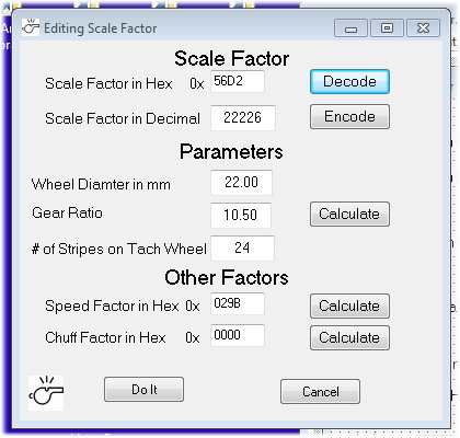
The diesel has the typical wheel that uses 22mm traction
tires. But when I measure the solid wheel without the tire, I get about
22.6 mm. It's a little tough to measure the wheel with the tire since
the measurement depends on how well the tire is installed. I measured a
few times and I could say that it might average around 22.6 mm.
Does anyone have any information as to whether or not I am
using the right values for the wheel or the gear ratio?
I got some responses to this as can be read on the OGR
Forum topic. I did some follow up research.
I opened up my 30-1660-1 P&LE (NYC) 0-6-0 USRA Steam
Switcher #9060 PS3 and twirled the tach wheel. I counted 18
revolutions for one rev of the driving wheel. The blind drivers and
non-traction tire wheels are 27mm. Again the traction tire increased
that a little bit to 27.2 mm. Tach tape has 24 stripes.
My goal along these lines is to figure out how to decode the
data returned by the engine that represents the trip odometer (DTO) and
odometer (DOD).
Step 1: a fixed distance
I used RR-Track when I designed my layout. RR-Track has the
ability to add up the length of a selected route. I picked my longest
circular route and RR-Track told me that it was 1.5884 Smiles. Ellison
fans will know that this was his term for a scale mile. In O gauge,
it's 110 feet or 1320 inches.
Starting with the diesel's wheel diameter at 22.6 mm, 24
stripes on the tach strip and a 10.5 gear ratio, math and geometry tell
us that we have 472.225 revolutions of the driving wheel to cover 1
Smile. That also works out to 119000.8 tach stripes per Smile.
My plan was to use that 1.5884 Smile distance as a standard
length to try to understand the DTO and DOD commands.
Step 2: Collect the data
For several years, I've been studying the commands and
responses between the remote and the engine. I learned a long time ago
how to build a radio snooper to decode the commands and responses. Both
the DTO and DOD commands elicit two responses from the engine, the
first is a 16 bit number, the second is a 32 bit number. These numbers
are read out from the RAM memory in the engine. The first number is
always the same for any particular engine and is the same for both the
DTO and DOD responses from that engine. The second number increases as
the engine runs and does not change when the engine is stopped. The
values returned for the DTO and DOD commands are very different but
both increase as the engine runs.
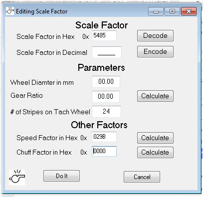
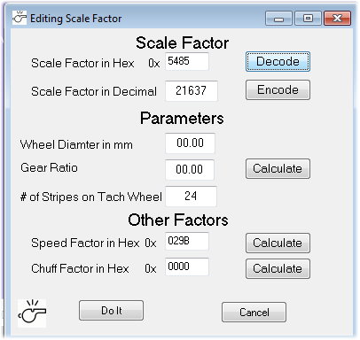
My working assumption is that the 16 bit number somehow
incorporates the gear ratio and wheel diameter. For the diesel that I'm
working with, the value is 21637. In a lot of my documentation, I call
this the Scale Factor.
Then the 32 bit number represents the trip odometer (for DTO)
and the odometer (for DOD). The remote takes these two values and
displays the Smiles on the display.
Step 3 : expectations
Scaling factor 16 bit value - I would expect this to be a
number that multiplies or divides the number to be scaled.
Like: actual value = initial value *
scaling factor
or: actual
value = initial value / scaling factor
In his reply above, Ted S, thinks this is not a 16 bit value
but rather two 8 bit values. He might be right.
DTO and DOD 32 bit value - This has to be derived from the
tach strip. In its simplest form, I would expect it to be a count of
tach pulses. I would expect the DTO value to be a lower value with a
lot of decimal places. A representation that could measure short
distances accurately. I would expect the DOD value to be a higher
number with few decimal places. A representation that could measure
long distances. Think about the number of digits on the odometer and
trip odometer in your car.
So if the DTO and DOD values were just a count of tach pulses,
we could expect that the scaling factor embodies the gear ratio and
wheel diameter to convert the raw values into linear distance.
Step 4: results
Now, running my engine over the measured 1.5884 Smile loop, I
got the scale factor, DTO and DOD values from the engine. I used the
remote to get these same values displayed as Smiles.
It took some experimenting and hints from Eric Linz, but I
came up with these two equations:
DTO in Smiles = raw_value / (11 * scaling_factor)
DOD in Smiles = (46.5 * raw_value) / scaling_factor
The constant factors in the equation were not exactly pulled
out of thin air but I can't explain their values. I got those values by
working backwards using the remote to tell me what DTO/DOD value I
should see.
Step 5: tests
Over my fixed loop, the DTO and DOD values using the equations
agree to within about 0.25% with the actual length of the loop. I
tested this with one diesel engine and one steam engine that had
different gear ratios and different wheel diameters. Both equations
agree with the remote down to a few decimal places (but don't produce
the exact same results as the remote).
I don't yet understand how to take a gear ratio and wheel
diameter to produce the scaling factor value.
That's all I have been able to figure out about DTO and DOD.
The sensor clearly has to be using something like the uP
counter input function, you could never individually capture all the
pulses otherwise. If the motor is spinning at 8,000 RPM (some
do, I checked), and you have 24 stripes, you'd have 3200 stripes/second
to sense, or one about every 300 microseconds. You might be
able to service interrupts at that pace, but it would be consuming a
significant part of the bandwidth.
I figure that for a typical diesel, there would be 119,000
pulses per Smile. At 120 Smph, that would be 238,000 pulses per minute
or 3966 pulses per second - one every 252 microseconds or so.
On a lower geared steam engine the pulse rate would be even higher.
So, as you noted, its likely this is a hardware
counter. But the DOD and DTO raw values are read out by
reading 4 bytes of RAM each. If these are hardware counters, they could
be memory mapped. I don't know what is available in whatever uP is used.
I have 16 engines and I've looked at the bytes at RAM 0x08 and
0x09 to try to see some pattern.
All diesels have Scale Factor values like 0x54 0xAB, 0x54 0x85 and 0x55
0x45. These all have about 22.6mm wheels.
The 4 steam engines have these values for Scale Factor and measured (as best as I can) wheel diameter:
0-8-0 0x5D
0x64 27.55mm wheel
2-8-0 0x62
0x55 32.74mm wheel
Berk 0x50
0x23 36.27mm wheel
0-6-0 0x7B 0x90
27.11mm wheel
Maybe there are some hints in these numbers.
Mark, I'm not sure that 0x09 has anything
to do with the
speed or odometer function. The byte at 0x08 does a pretty
good
job by itself of describing the effective gear
ratio and by extension, motor revolutions per inch, stripe count per
inch, stripe count per second at a given speed, etc.
Your sample data only confirms what I already
knew. All diesels are geared the same at 10.5:1 and typically
have the same size wheels.
The formula for the approximate gear ratio is: Driving Wheel
size
in mm * the value of 0x08h as an 8-bit integer * 0.00552.
I'm not sure why some diesels have 0x54 and others
0x55. But the difference is only 1 in 84, or about 1.1
percent which is within tolerances for double-heading.
I also can't explain why the formula
doesn't work out to the exact value in every case.
Ted, I'm going to spend some time considering your point about
the byte at 0x08. I can modify RTC to use only that byte in the DTO and
DOD calculations. I'll post my results.
The one strong point against it (at least to me) is that when
the remote reads up the scale factor, it always reads up two bytes.
Reading bytes out of RAM is fairly expensive in terms of bandwidth over
the track. In every command that I've looked at, the remote never reads
up any extra bytes. If it could work with just the byte at 0x08, it
would not have read up the byte at 0x09.
Ted, I appreciate all of your comments. Makes me
think further.
I ran a bunch of comparisons today between my equations and
the remote. I am using the scale factor as a 16 bit number. My
equations are:
DTO = ((RawValue) / ((ScaleFactor) * (11)))
DOD = (((46.5) * (RawValue)) / (ScaleFactor))
To come up with these equations, I first guessed that the raw
value had to be divided by the scale factor. Then there needed to be a
constant to get the correct value. I used a comparison with the value
generated by the remote, worked backwards and found the constants
needed. It amazes me how well these constants work in the equations as
shown in the comparisons below. I can't explain the significance of
these constants.
I'm still looking at the scale factor and how it could be
derived from the gear ratio and driving wheel diameter
DOD
11 Sep 2019

Engine	RTC	Remote
1 	646.41	646.4	U28B
4 	297.30	297.3	SW1200
4 	298.16	298.2
5 	162.29	162.3	2-8-0 H9
5 	163.41	163.4
6 	159.58	159.6	Berkshire
11 	290.29	290.3	0-6-0
11 	290.55	290.6
13 	100.52	100.5	GP7
14 	38.73	38.7	GP38-2
14 	40.92	40.9

DTO
11 Sep 2019

Engine	RTC	Remote
1 	0.25967 0.3 	U28B
4 	0.88183 0.9 	SW1200
4 	1.73594 1.7
5 	1.11786 1.1 	2-8-0 H9
6 	0.40387 0.4 	Berkshire
6 	1.09274 1.1
11 	0.25700 0.3 	0-6-0
11 	0.51748 0.5
13 	1.55870 1.6 	GP7
13 	2.08773 2.1
14 	2.19460 2.2 	GP38-2
Perhaps another way to
look at it is to observe that 46.5 x 11 = 511.5. That is
suspiciously close to "exactly" 512.000 - in other words is a 9-bit
binary shift which is arguably what you'd expect a presumably
fixed-point microcontroller processor to do to represent two levels of
resolution or scaling of the same underlying value.
Stan, you may be on to something here. The 46.5 number I use
was derived by working backwards. With a little more 'tuning', it
really could be 46.545454 and then 46.545454 * 11 = 512.
X is the
same raw_value (tach stripe count). Different slopes and
different offsets but with a fixed-ratio (512) between m1 and m2.
Stan, I can easily test this part.
I took the DTO and DOD raw values, ran the engine for about
1.5 Smiles and took the raw values again:
| |
Start |
End |
Difference |
| DTO |
0 |
392296 |
392296 |
| DOD |
27117 |
27883 |
766 |
The DTO difference is (almost) exactly 512 times the DOD
difference. Its off by just a little which could be the result of how
the engine accumulates the tach counts.
So you have added another piece of the puzzle.
I did some calculations using the measured gear ratio,
measured diameter of the driving wheel and the observed number of
stripes on the tach strip. I was able to determine the number
of tach stripes per Smile. For a typical diesel, this was 119000
stripes per Smile (it is different for each gear ratio and wheel
diameter).
I ran the engine for as close to 1 Smile on my layout as I
could (1 Smile is 110 feet). I read up the raw DTO value and raw DOD
value at the beginning and end of that run.
For DTO, the raw value delta over 1 Smile is 237012, for DOD,
the raw value delta over 1 Smile is 462.
Looking at these numbers shows that 237012 is about 2 * 119000
and 462 is about 119000 / 256. I confirmed this general pattern with
two other engines with different gear ratios and wheel diameters.
This tells me that for the DTO, each tach stripe generates two
raw tach counts, possibly a count for the white to black edge and a
count for the black to white edge.
The DOD raw value is just the DTO raw value divided by 512 (8
fewer significant bits, yes 8, not 9).
Your sample data only confirms what I already
knew. All diesels are geared the same at 10.5:1 and typically
have the same size wheels. With my understanding, and never
having had any of your locos apart, I predict the gear ratios of your
steamers as follows: 0-8-0 is 14:1, 2-8-0 is 18:1, Berk is
16:1 (I'm guessing yours is Premier- I have one), 0-6-0 is
18:1.
You are exactly right!
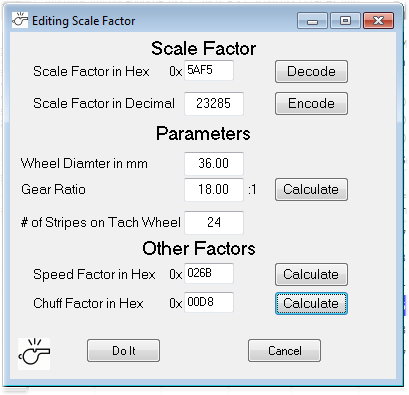
I have developed an equation which I think will let you
calculate the gear ratio from the Scale Factor Value, the measured
wheel diameter and the number of stripes per rev of the tach wheel
(usually 24). The measured wheel diameter is the real variable in this
equation. Its hard to measure with the traction tire in place. But its
the traction tire that really determines how far the engine goes in one
rev of the driving wheel.
Here are the values that I get which need to be rounded:
0-6-0 18.41 (I actually twirled the tach
wheel and counted 18:1 on this engine)
2-8-0 17.86 (you predicted 18:1)
Berkshire 15.98 (you predicted 16:1)
0-8-0 14.14 (you predicted 14:1)
The equation can also be solved for the Scaling Factor given
the gear ratio, the wheel diameter, and the number of stripes per
revolution of the tach wheel.
I've updated my ADPCM program to let you calculate and update
the scale factor value in your engine. Given the wheel diameter, gear
ratio, and number of stripes, it calculates the value and writes it to
a sound file. Then you can download the sound file into the engine.
It needs to be tested. If any one has an actual situation
where the scale factor calculation can be confirmed, I will make the
new version of ADPCM available to them.