What is on the tag?
The first 16 bytes of data in the tag (in what is known as block 4 in
the tag memory) contains the following
information (you don't need to know the numeric values shown, the Tag
Programmer will set that for you correctly):
TagID
TAG_NOT_PROGRAMMED 0x00
TAG_PROGRAMMED 0x88
EngineNo
0 = not an Engine or LashUp (look at
CarModel),
otherwise DCS Engine Number 1-99 (look at CarModel) or
101-120 LashUp
Number
NOT_AN_ENGINE 0
TagLocation
NOT_ON_A_TRUCK 0
TAG_ON_FRONT_TRUCK 1
TAG_ON_REAR_TRUCK 2
TAG_UNKNOWN 3
TAG_ON_TRUCK 4
TAG_AT_MIDPOINT 5
EngineType
NOT_AN_ENGINE 0
DIESEL_ENGINE_TYPE 1
STEAM_ENGINE_TYPE 2
GAS_MECHANICAL_ENGINE_TYPE 3
GAS_ELECTRIC_ENGINE_TYPE 4
STEAM_TURBINE_ENGINE_TYPE 5
ELECTRIC_TYPE 6
TURBINE_TYPE 7
DIESEL_MECHANICAL_TYPE 8
Coupler
Specifies
the location and operation of the couplers
NO_COUPLER 0
REAR_REMOTE_COUPLER_ONLY 1
FRONT_REMOTE_COUPLER_ONLY 2
FRONT_AND_REAR_REMOTE_COUPLERS 3
COUPLER_UNKNOWN 4
REAR_MANUAL_COUPLER_ONLY 5
FRONT_MANUAL_COUPLER_ONLY 6
FRONT_AND_REAR_MANUAL_COUPLERS 7
REAR_DUMMY_COUPLER_ONLY 8
FRONT_DUMMY_COUPLER_ONLY 9
FRONT_DUMMY_AND_REAR_MANUAL_COUPLERS 10
NOT_APPLICABLE 0x80
SXS
0 = no SXS
Sound, 1 = has SXS sound at clip 42 (Engines only)
NO_SXS_SOUND 0
HAS_SXS_SOUND 1
Engine/Car Model
if EngineNo is equal to
NOT_AN_ENGINE
UNKNOWN_CARMODEL 0
BOXCAR 1
TANK_CAR 2
FLAT_CAR 3
CABOOSE 4
TENDER 5
GONDOLA 6
COAL_HOPPER 7
ORE_HOPPER 8
MOW_FLATCAR 9
MOW_CRANE_CAR 10
MOW 11
COACH 12
OBSERVATION 13
BAGGAGE 14
if EngineNo is not equal to
NOT_AN_ENGINE (Lead Engine for LashUps)
UNKNOWN_ENGINEMODEL 0
GP38_2 1
GP7 2
GP9 3
U28B 4
BERKSHIRE 5
DOODLEBUG 6
SW1200 7
SW1500 8
SWITCHER_0_6_0 9
SWITCHER_0_8_0 10
H_9 11
SW_9 12
RS_3 13
MP15DC 14
Railroad
UNKNOWN_OR_OTHER 0
P_AND_LE 1
A_AND_S 2
NYC 3
B_AND_O 4
P_AND_E 5
LE_AND_E 6
P_RR 7
NH 8
RDG 9
J_AND_L 10
Isalys 11
LV 12
Many more are defined. See "Tag Programmer" Engine Model drop-down list
CarLength
Length of engine/car in centimeters, coupler face
to
coupler face (include Tender). In the Tag Programmer, you enter this
distance in inches.
TagOffset
Distance from center of tag to coupler face in
centimeters. In the Tag
Programmer, you enter this distance in inches.
For
engines/cars with two tags, the distance must be same for both tags
CarNumber
Up to 6
digit engine/car number in ASCII (w/leading spaces). Example:
" 2808"
The second 16 bytes of data in the tag (in what is known as block 5 in
the tag memory) contains the name of engine or car (in
whatever
format you care to use).
example : "A&S SW1200 #1208"
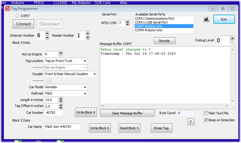
The Programmer
The tag programmer uses the same Arduino/PN532 Reader as is used in the
tag detection system. When you start the program, you should see this
screen (although the values in each may be different as I've used this
copy of the program to write data to many tags)
First, set the RFID COM port value. This is the USB COM port that was
selected when you plugged the Arduino's USB cable into the PC. For my
computer it is COM7.
Then press the [
Connect]
button.
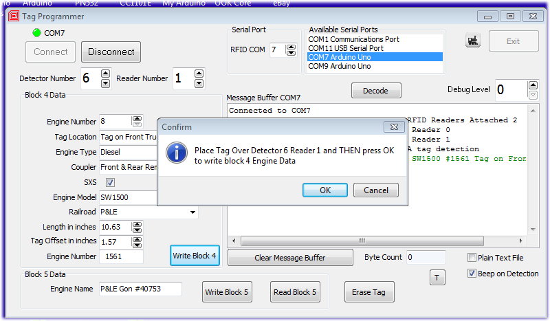
The program connects up with the Arduino and shows its number (6) and
how many RFID tag readers are attached to it.
At this point, the program is a simple tag reader. You can pass any tag
over any connected reader and the program will display information
about that tag:
I passed a tag from P&LE engine#1561 (my DCS engine #8) over
the RFID tag reader #1 on Arduino detector board #6.
To get ready to write data to the tag, set the
Detector Number and
Reader Number in the
spinners (in my screen shot, they are already set to 6 and 1 but that
will probably not be the case on your computer).
Next, create the 16 bytes of data to be written into block 4 on the
tag. Some of these fields, you can type in a number, select an item
from a drop-down list or type in words. Here is what each field means:
- Not an Engine/Engine Number - set to 0 if it is a car
rather than an engine otherwise set to the DCS engine number
- Tag Location - select from the drop-down list
- Engine Type - if it is an engine, select the engine type
from the drop-down list
- Coupler - select from the drop-down list.
- SXS - if it is an engine, select if it has the SXS sound
- Engine/Car Model - select the model from the drop-down list
- Railroad - select the Railroad name from the drop-down list
- Length in Inches - the distance in inches between the
coupler faces
- Tag Offset in Inches - the distance in inches from where
you mounted the tag to the nearest couple face
- Engine/Car Number - 6 characters that represent the actual
number on the side of the consist.
Then press [
Write Block 4].
The program will ask you to place the tag over the tag reader (actually
tag writer). When you do this, the tag will read up what ever is
already programmed in it. Then press the [
OK] button.
That's it.
Next create the 16 characters of Engine/Car name to be written into
block 5 of that tag. Up to 16 characters and can be any
characters/numbers/special characters on your keyboard.
Then press [
Write Block 5].
The program will ask you to place
the tag over the tag reader (actually tag writer). When you do this,
the tag will read up what ever is already programmed in it. Then press
the [
OK]
button.
When you are done, press [
Disconnect]
and then [
Exit].
Some other features:
[
Clear
Message Buffer] will clear out the Message Buffer
[
Read
Block 5] will cause the tag reader to read up block 5
instead of block 4 (which is the normally done)
[
Erase
Tag] will erase all of the engine/car data from the tag
[
Decode]
will take the information from the last tag read and put the data into
the input fields
[x]
Beep
on Detection causes the program to beep each time a tag is
place over a reader
[
T]
places a time stamp into the Message Buffer
Debug
Level spinner causes the program to display more
information as it runs.
Right click in Message Buffer lets you
select and save all or part of the Message Buffer
 Customizing the Tag Programmer for your Layout
You may have noticed that the dropdown lists presented by the Tag
Programmer only contain selections for my layout. Well, you can
customize the programmer for your layout.
The first time that you run Tag Programmer, it will create 5 files in
its folder:
-
CarModels.txt
-
EngineModels.txt
-
EngineTypes.txt
-
RailroadNames.txt
-
TagLocations.txt
These files contain the selections presented by the dropdown lists.
Each line in each file is one selection. For example, here is the
RailroadNames.txt file:
|
RailroadNames.txt
file
Unknown or other
P&LE
A&S
NYC
B&O
P&E
LE&E
PRR
NH
RDG
J&L
Isalys
LV
AC
ATSF
AC
BAR
B&A
BM
BCR&N
BN
BNSF
CPRR
CNJ
CSX
CV
CO
CBQ
MILW
CGW
RI
CNW
C&S
CR
D&RG
D&RGW
DTI
EJ&E
EL
Erie
GT
GN
IC
LN
MCR
MSTL
MKT
MP
NS
OW
NKP
NS
NW
NP
PC
SAL
SP
SPSR
SPSF
TNO
WM
WP
WC
PRC
|
The first item in the file is the first selection presented in the
dropdown list. Internally, it will become selection 0. Before you start
programming your tags, you can edit this file (using a text editor like
notepad, metapad or notepad++) to add or change railroad
names.
You can do same for the other 4 files. I would suspect that you would
not want to edit the EngineTypes.txt or TagLocations.txt files as they
are pretty well defined (but you still can if you want to). The CarModels.txt and EngineModels.txt are
good candidates for editing. Here are those files:
|
CarModels.txt
file
Unknown or other
Boxcar
Tank
Flat
Caboose
Tender
Gondola
Coal Hopper
Ore Hopper
MOW Flat
MOW Crane
MOW
Coach
Observation
Baggage
|
|
EngineModels.txt
file
Unknown or other
GP38-2
GP7
GP9
U28B
Berkshire
Doodlebug
SW1200
SW1500
0-6-0
0-8-0
2-8-0 H9
SW9
RS-3
MP15DC
PCC
|
|
EngineTypes.txt file
Not an Engine
Diesel
Steam
Gas-Mechanical
Gas-Electric
Steam Turbine
Electric
Turbine
Diesel-Mechanical
|
|
TagLocations.txt file
Tag not on Truck
Tag on Front Truck
Tag on Rear Truck
Tag Location Unknown
Tag on Truck
Tag at Midpoint
|
As you program tags, just remember that the tag does not contain the
words in these files, it contains only the numerical index (starting at
0) of the item that you selected. So once you start editing these
files, don't change a previously used item unless you want that change
to be reflected in all tags.
Now, the most useful part of these files is each time that you edit
them, you should copy them to the folder that contains the Remote Train
Control (RTC) program. Then when you start the RTC program, it will
notice these files and it will use them for all of its decoding on the
Program Control windows.