 Background
 I
started development of this web page in January 2025. It will be under
construction for a while.Background The
ESP8266My Ideas
I
started development of this web page in January 2025. It will be under
construction for a while.Background The
ESP8266My Ideas
RTCAdapter Version 1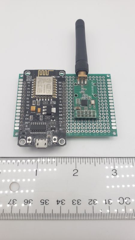 |
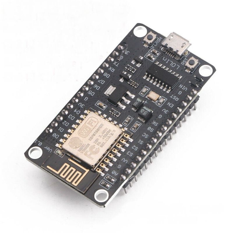
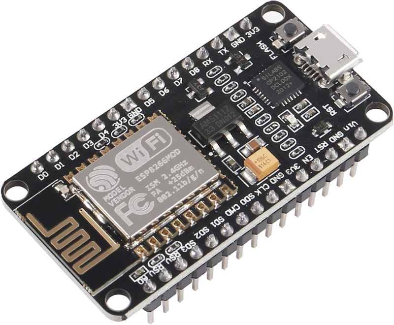
An ESP8266 with a CC1101E radio (from Elechouse)
attached. This is
needed for RTCAdapter script. https://www.elechouse.com/product/915mhz-cc1101-wireless-module/ The illustration shown on this site is labeled RF1100SE but this specific 915Mhz version is V3.1. This can be powered with a USB cable plugged into a USB port (on your computer or on the WTIU itself) or directly from a 5 volt wall wart. |
||||||||||||||||||||||||||||||||||||
 |
Wiring side of the ESP8266 + Elechouse radio board.
|
||||||||||||||||||||||||||||||||||||
| RTCAdapter Version 2 |
An ESP8266 with a CC1101E radio (E07-900M10S 8 pin
version from Darrell Lamm) attached. Get it from : https://www.ebay.com/itm/144715454017 There is also a 10 pin version of this radio with the same pinout as the Elechouse board. Either one will work : https://www.ebay.com/itm/146353854626 |
||||||||||||||||||||||||||||||||||||
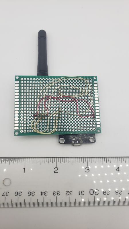
Wiring side of the ESP8266 +
E07-900M10S radio board. Note that this radio uses an 8 pin
interface, just a little different than the 10 pin interface of the
Elechouse radio (but all the same signals).
|
|||||||||||||||||||||||||||||||||||||
|
RTCAdapter Version 3
|
An ESP8266 with a CC1101E radio (E07-900M10S 8 pin
version from Darrell Lamm) attached using female-female Dupont
Wires. Get the radio from : https://www.ebay.com/itm/144715454017 The 10 pin version of this radio will also work fine: https://www.ebay.com/itm/146353854626 This is a good quick and easy test bed that does not require soldering or wirewrap. These Dupont wires are not that great of a connection and since they are just push on, they can fall off. Find a more secure way to interconnect these devices for the longer term.
FWIW: These wires were first made by Berg Electronics which was sold to DuPont and is now owned by Amphenol. Pins are 0.025 x 0.025 inches square. |
Parts
SourcesRTC WiFi Adapter (sketch in file
RTCAdapter.ino)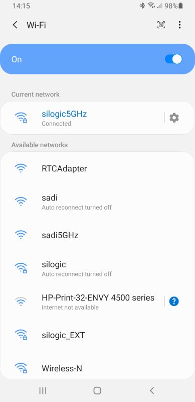 |
After you upload the
RTCAdapter sketch into the ESP8266, it will
start an Access Point. If you look on your phone, you will see the new
WiFi
AP listed as RTCAdapter. Touch on that AP to connect to it. |
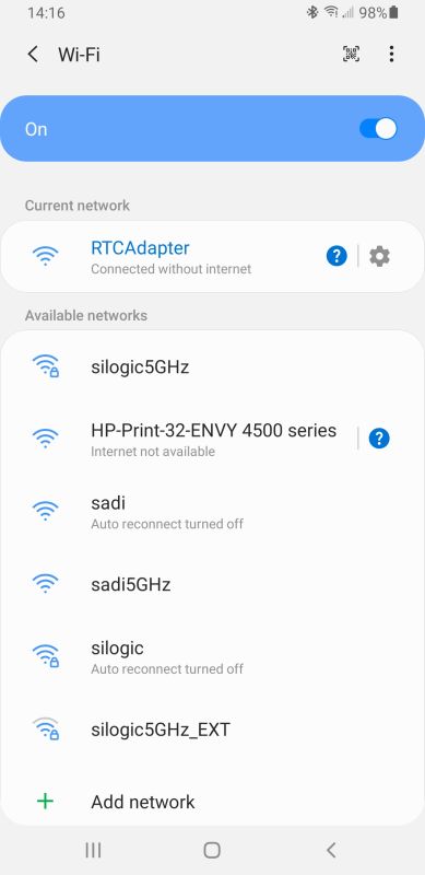 |
The
phone should connect up and you should see "RTCAdapter
Connected without internet". If your phone can't seem to maintain the network connection, look for a prompt asking if you want to stay connected even though an internet connection is not available. When you get that prompt, press "Stay Connected". |
|
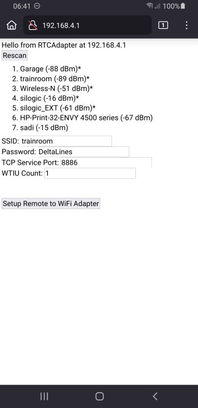
For RTCAdapter version 1.09 and earlier Then startup a web browser. Enter this IP address into the Address Bar: 192.168.4.1 . Press GO. You should see this screen which lists all of the accessible WiFi routers in the area. Here is were we enter the information that the RTCAdapter sketch needs to communicate with your WTIU via the WiFi router. Enter: The SSID of your router The WiFi password of your router The TCP Service port of this device (don't change this). The number of WTIU's that RTCAdapter should connect to (not the WTIU number). Then click on [Setup Remote to WiFi Adapter]. |
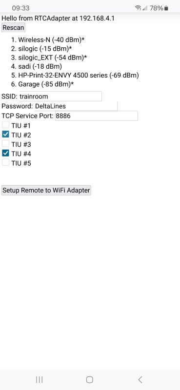 |
For RTCAdapter version 1.10 and newer Then startup a web browser. Enter this IP address into the Address Bar: 192.168.4.1 . Press GO. You should see this screen which lists all of the accessible WiFi routers in the area. Here is were we enter the information that the RTCAdapter sketch needs to communicate with your WTIU via the WiFi router. Enter: The SSID of your router The WiFi password of your router The TCP Service port of this device (don't change this). The active WTIU on your layout. Check each box if the WTIU is present. (You can pinch zoom in to make checking the boxes a little easier.) Then click on [Setup Remote to WiFi Adapter]. |
|
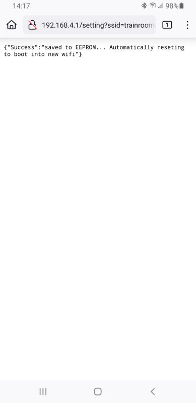
You
should see this screen indicating that the device has saved your
information, is rebooting and will connect up the WiFi Router. The ESP8266 will reboot and start. If the LED on the board stays on, the board is having trouble connecting to the router. If the LED blinks, the board is having trouble finding the number of WTIU that you specified. If you need to change these setting after first setting them, press the ESP8266 reset button twice a few seconds apart. The ESP8266 will then let you go through these setup steps again. |
1. The
Adapter acts as a relay between the Remote and the WTIU. It listens for
commands from the Remote using a 915Mhz radio, translates those commands as
necessary for the WTIU and then sends them to the WTIU over WiFi.
1. The
Adapter not replace the App. This Adapter only does the easy stuff. You
will need the App to do
the hard stuff. Adapter lets you add engines, runs engines and
lashups and controls the AIU. At the top of this web page is a list of
what it does not do. Only works with the WTIU, does
not work with the WIU as the WIU/TIU combination already has radio
based
control from a Remote.
1. I’m
always looking for feedback on the Adapter. I’ve believe most engine and lashup
functions work. I’m less sure about Super TIU Mode. I’ve gotten inconsistent
results with that. Let me know what works for you and what doesn’t. I’ll do my
best to fix the bugs.
Getting the sketches into an ESP82661. RTCAdapter : loading pre-compiled binary code
using RTCAdapter-X.XX.zip and COMx port| E:\Projects\ESP8266\RTCAdapter>rem E:\Projects\ESP8266\RTCAdapter>rem USB E:\Projects\ESP8266\RTCAdapter>"C:\Users\markd\AppData\Local\Programs\Python\Python312\python" -I "upload.py" --chip esp8266 --port "COM3" --baud "115200" "" --before default_reset --after hard_reset write_flash 0x0 "build\esp8266.esp8266.nodemcuv2/RTCAdapter.ino.bin" esptool.py v3.0 Serial port COM3 Connecting..... Chip is ESP8266EX Features: WiFi Crystal is 26MHz MAC: c8:c9:a3:56:63:4b Uploading stub... Running stub... Stub running... Configuring flash size... Auto-detected Flash size: 4MB Compressed 408992 bytes to 292129... Wrote 408992 bytes (292129 compressed) at 0x00000000 in 25.7 seconds (effective 127.1 kbit/s)... Hash of data verified. Leaving... Hard resetting via RTS pin... E:\Projects\ESP8266\RTCAdapter>rem E:\Projects\ESP8266\RTCAdapter>pause Press any key to continue . . . |
2. RTCAdapter : loading pre-compiled binary code
using RTCAdapter-X.XX.zip and the HTTPUpdater (with a browser like Firefox or Chrome)3. RTCAdapter : compiling
source code using RTCAdapter-X.XX.zip and a COMx port.| Using library ESP8266WiFi at version 1.0 in folder:
C:\Users\XXXX\AppData\Local\Arduino15\packages\esp8266\hardware\esp8266\3.1.2\libraries\ESP8266WiFi
Using library ArduinoOTA at version 1.0 in folder: C:\Users\\XXXX\AppData\Local\Arduino15\packages\esp8266\hardware\esp8266\3.1.2\libraries\ArduinoOTA Using library ESP8266mDNS at version 1.2 in folder: C:\Users\\XXXX\AppData\Local\Arduino15\packages\esp8266\hardware\esp8266\3.1.2\libraries\ESP8266mDNS Using library EEPROM at version 1.0 in folder: C:\Users\\XXXX\AppData\Local\Arduino15\packages\esp8266\hardware\esp8266\3.1.2\libraries\EEPROM Using library SPI at version 1.0 in folder: C:\Users\\XXXX\AppData\Local\Arduino15\packages\esp8266\hardware\esp8266\3.1.2\libraries\SPI Using library ESP_DoubleResetDetector at version 1.3.2 in folder: C:\Users\XXXX\Documents\Arduino\libraries\ESP_DoubleResetDetector Using library LittleFS at version 0.1.0 in folder: C:\Users\\XXXX\AppData\Local\Arduino15\packages\esp8266\hardware\esp8266\3.1.2\libraries\LittleFS Using library FIFObuf at version 1.1.2 in folder: C:\Users\XXXX\Documents\Arduino\libraries\FIFObuf Using library CC1101E_OOK_ESP at version 1.0.0 in folder: C:\Users\\XXXX\Documents\Arduino\libraries\CC1101E_OOK_ESP Using library CC1101E_OOK_ESP_SPI at version 1.0.0 in folder: C:\Users\\XXXX\Documents\Arduino\libraries\CC1101E_OOK_ESP_SPI Using library ESP8266HTTPClient at version 1.2 in folder: C:\Users\\XXXX\AppData\Local\Arduino15\packages\esp8266\hardware\esp8266\3.1.2\libraries\ESP8266HTTPClient Using library ESP8266WebServer at version 1.0 in folder: C:\Users\\XXXX\AppData\Local\Arduino15\packages\esp8266\hardware\esp8266\3.1.2\libraries\ESP8266WebServer Using library ESP8266TimerInterrupt at version 1.6.0 in folder: C:\Users\\XXXX\Documents\Arduino\libraries\ESP8266TimerInterrupt Using library EspSoftwareSerial at version 8.0.1 in folder: C:\Users\\XXXX\AppData\Local\Arduino15\packages\esp8266\hardware\esp8266\3.1.2\libraries\SoftwareSerial |
4. RTCAdapter : compiling
source code using RTCAdapter-X.XX.zip and use the OTA (Over the Air) upload. Childproof
ModePossibly Useful
Tools to Help Get your WTIU On-Line - WIU Packet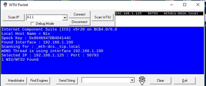
The [Find Engines] button will ask the TIU about the engines connected to it. You will see all of the engines that are associated with that TIU.
The [Send String]
button will send whatever string you type in the box to the TIU. Don't
use this unless you know the TIU commend set. This spreadsheet
describes the TIU command set.
Checking the "Debug Mode" checkbox will display a lot of technical
information that may not be useful.
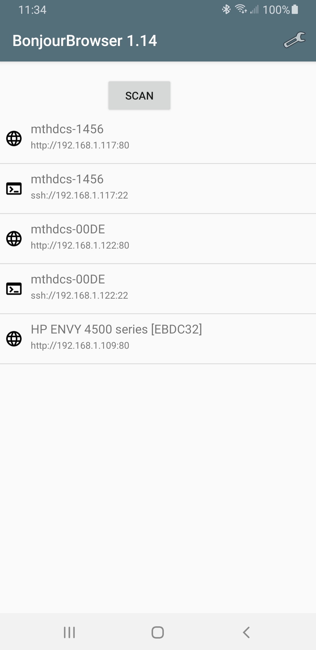
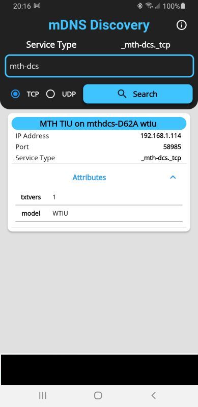
Another tool that runs on Android (and probably iPhones) smart phones. The program "Bonjour Browser" can search for local devices on your WiFi network like printers, scanners and .... WIU and WTIU.
Run the program on your cell phone and you should see something like this:
 Debugging Hints
The Free
Software Foundation
web page talks about what "free software" means.
For more information, look on the Open Source Initiative web site which includes a description of what Open Source means and their certification of the GPL version 3.
Here is the copyright notice for those two licenses:email : markd@silogic.com
The DiVecchio
genealogy home page
The Frazzini
genealogy home page
This site will be under construction for a while.